KE2010.Instruction Manual.Ver.2.01,Rev.08.pdf - 第601页
8 − 12 5) Controlling the blow This item turns on and off of the blow of the head select ed. W hen the control item “Blow cont.” is checked, click one of the <ON) >, <OFF> and <ON/O FF> buttons, or pres…
8 − 11
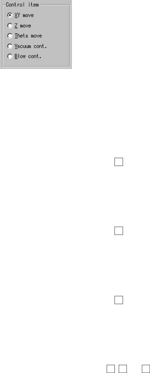
(2) Control item
Select the control item with a radio button.
(3) Control button
Each control item can be executed with the corresponding control button.
The display of the control buttons differs depending on the control item
selected.
1) Moving the X- and Y- axes
When the control item “XY move” is checked, enter the destination
coordinates, then click the <EXEC> button or press the F3 key. The head
starts moving by referring to the selected control unit position.
The display of the coordinates is updated when the movement has been
completed.
2) Moving the Z axis
When the control item “Z move” is checked, enter the destination
coordinates, then click the <EXEC> button or press the F3 key. The head
starts moving by referring to the selected control unit position.
The display of the coordinates is updated when the movement has been
completed.
3) Moving the θ axis
When the control item “Theta move” is checked, enter the destination
coordinates, then click the <EXEC> button or press the F3 key. The theta
axis starts moving by referring to the selected control unit position.
The display of the coordinates is updated when the movement has been
completed.
4) Controlling the vacuum
When the control item “Vac. cont.” is checked, click one of the <ON>,
<OFF)> and <ON/OFF> buttons, or press one of the F3, F4 and F5 keys.
The display of the vacuum level is updated when the control has been
completed.

8 − 12
5) Controlling the blow
This item turns on and off of the blow of the head selected.
When the control item “Blow cont.” is checked, click one of the <ON)>,
<OFF> and <ON/OFF> buttons, or press one of the F3, F4 and F5 keys.
The display of the vacuum level is updated when the control has been
completed.
(4) State display
X and Y coordinates, Z coordinate, θ coordinate, and pressure value are
displayed when the control has been completed.
The pressure value is always displayed during monitoring.
8 − 13
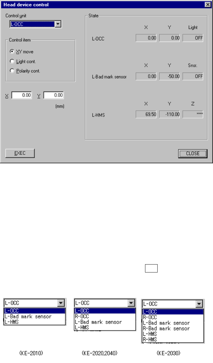
8.2.2 Head device control
When you select the [Head] command on the [Ctrl] menu, then the [Head device
control] command, the following Head device control dialog box appears on the
screen.
Figure 8.2.2 Head device control dialog box
(1) Control unit
Select the unit to be controlled from the combo box.
You cannot select any unit which is not checked (not installed) at the “Option”
setting of the MS parameters.
This selection does not affect the setting of the “Device enable” menu invoked
from the Machine Setup menu. (This means that the units not checked (not
used) can be used.)
The following list appears when you press the ALT key and the down arrow key
at the same time.