KE2010.Instruction Manual.Ver.2.01,Rev.08.pdf - 第277页
4 – 170 Figure 4.10.2. 3 Divided Placement Data Displ ay Example (O ptimization Order) Note: When displayed in optimization order , the pair end mark “/ ” indicates the separation of data paired during one pick and place…
4 – 169
4.10.2 Divided Placement Data
This command displays Placement data which is distributed to each station by the
Optimization utility. Select the menu command [Divided Placement Data] from the
“Optimization” menu. A submenu from which you can select stations displays. Select
a station whose data is to be displayed.
Figure 4.10.2.1 Divided Placement Data selection menu
Notes:
①
This menu cannot be selected if optimization has not been performed
(the divided files do not exist), or if the production program has been
changed after optimization.
②
The system can display Divided Placement data in two orders: input
order and optimization order. Select the menu command [File], and then
[Environment setting] command on the “File” menu to select the order.
•
When you select the input order, the system displays all Placement
data in input order.
•
When you select the optimization order, the system displays only the
Placement data that is used to place components in optimized
placement order with considering the optimization result.
When you select a station on the station selection dialog box, the corresponding
window appears on the screen as shown below.
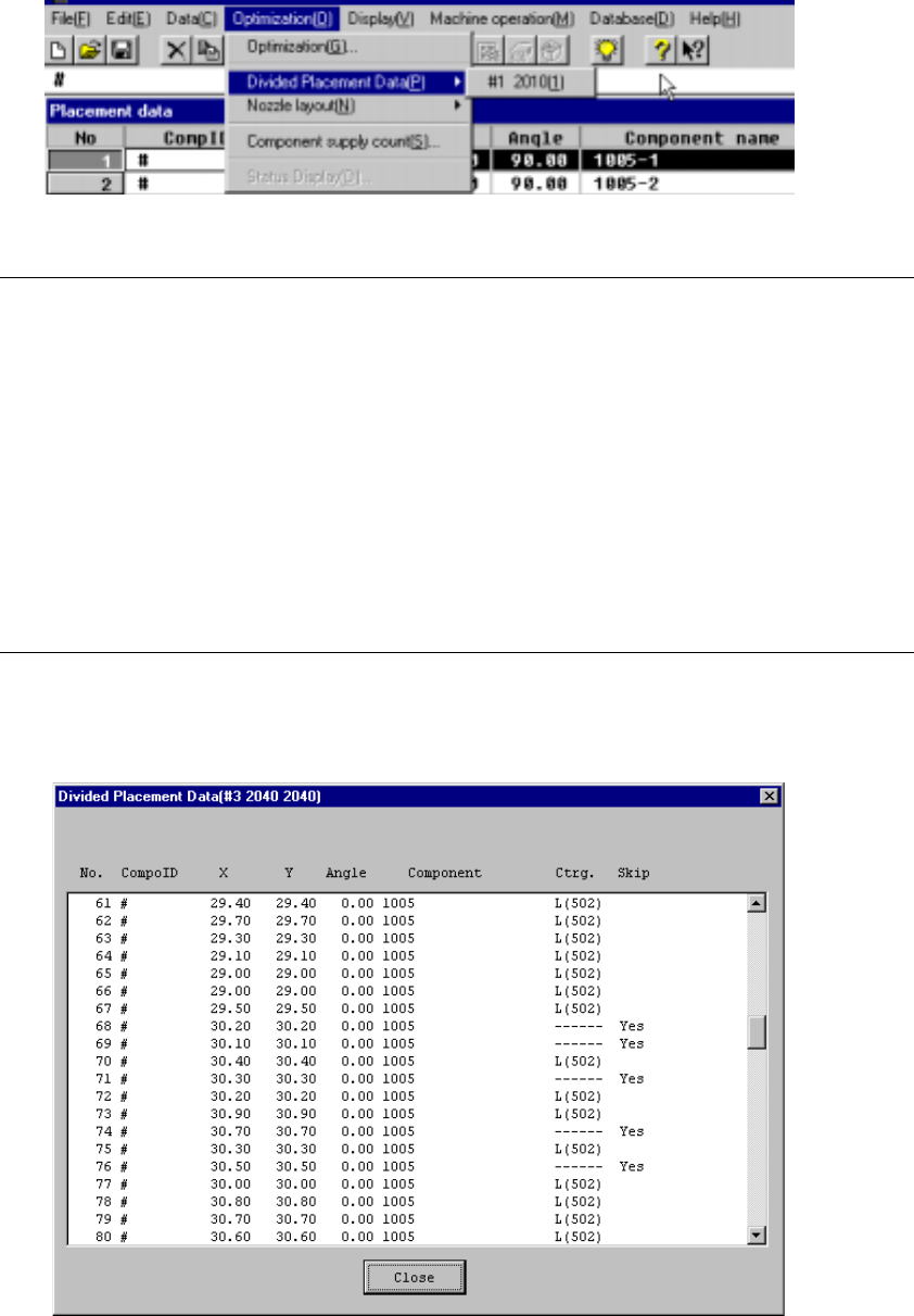
Figure 4.10.2.2 Divided Placement Data Display Example (Input Order)
4 – 170
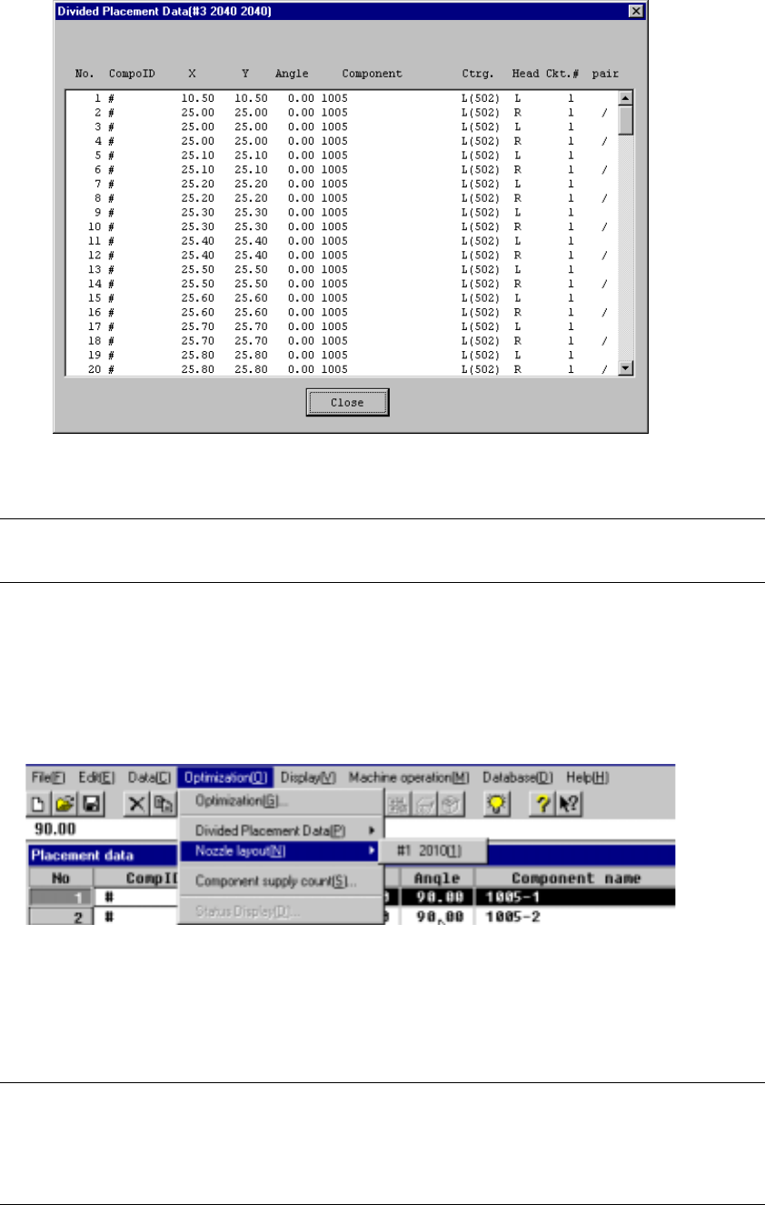
Figure 4.10.2.3 Divided Placement Data Display Example (Optimization Order)
Note: When displayed in optimization order, the pair end mark “/” indicates the
separation of data paired during one pick and placement cycle of operation.
4.10.3
Nozzle layout
This command displays the nozzles assigned to each station by the Optimization
utility.
Figure 4.10.3.1 Nozzle Layout Selection
Select the “Nozzle Layout” menu command from “Optimization” menu. The sub-menu
appears which allows you to select a station. Select the desired station on this
sub-menu.
Notes:
①
This menu cannot be selected if optimization has not been preformed or
if the production program has been changed after optimization.
②
Nozzle displayed here are nozzles that are set in the Machine setup
menu and nozzle used in the program data.
4 – 171
The following window displays after a station is selected:
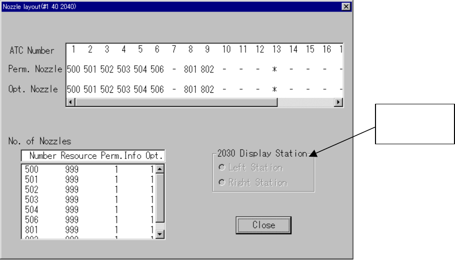
Figure 4.10.3.2 Nozzle Layout Display Example
• Perm. Nozzle (Permanent nozzle):
Nozzle layout which is set on the Machine setup menu.
( * mark indicates the vacuum calibration.)
• Opt. Nozzle (Optimized nozzle):
Nozzle layout which is output with the Optimization utility.
( * mark indicates the vacuum calibration.)
• No. of Nozzles:
Number of nozzle resources (Resource), the number of nozzles set as
the permanent information (Perm. Info) and the number of nozzles output
with the Optimization utility (Opt.) are displayed here.
• Close: Quits the Nozzle layout dialog box.
Enabled for
KE-2030 onl
y