KE2010.Instruction Manual.Ver.2.01,Rev.08.pdf - 第376页
5 − 23 ⑤ Pattern whose scale (size) and/or ang le changes Especially if a par t of the patt ern is specif ied as the user def ined te mplate, change of the scale aff ects the r ecognition accur acy . T heref ore, specif …
5 − 22
5) To store the production program which uses the user defined template on the
floppy disk, check to see if there is enough space for it. If there is not sufficient
space on the disk, a production program may not be stored.
6) Since it takes a long time for the production program which uses the user defined
template to be read from or store on the floppy disk, it is recommended that the
production program is not read nor stored from/onto the floppy disk directly.
7) To copy the production program which is stored on the hard disk, select the [File
Management (Explorer)] command on the [File] menu invoked from the main
menu to copy it onto a floppy disk.
Patterns which can be registered as the user defined template
− Patterns which can be registered as the user defined template
① Wiring pattern
② Pad and land pattern where no screen is printed (no solder paste is put)
③ PWB marks other than JUKI standard marks (whole or part)
− Notes on registration as the user defined template
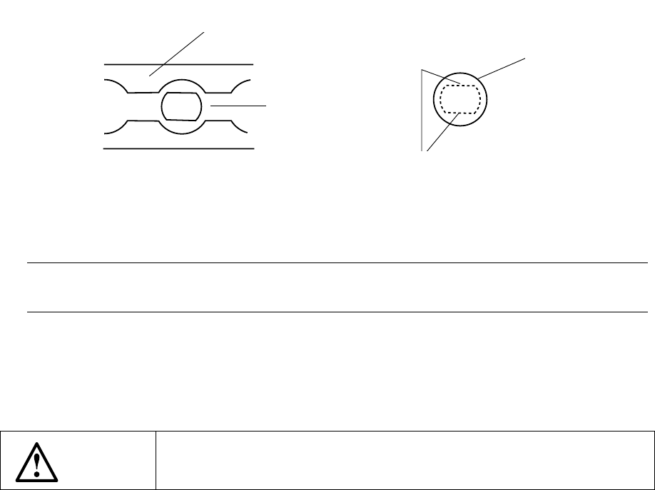
① Through hole and pier hole
Since the pattern generation process is different from the holing process, the
same positioning cannot be always achieved. (The hole position is
undefined for a pattern.)
To register the template based on the through hole or pier hole, include the
wiring pattern around the hole.
− Pattern which cannot be registered as the user defined template
① Silk (character) pattern
Since the pattern and pad generation process is totally different from the silk
printing process, the placement position cannot be determined based on the
silk print.
② Pad and land pattern printed on the silk screen
The solder paste on the screen is in the form of grains, so lighting cannot be
stable depending on the environment or condition. The template matching
is highly appropriate for change of lighting conditions, but not for the change
of polarity (positive and negative).
③ The similar pattern is located on the same recognition screen
④ The template whose difference between the brightness and the darkness is
little.
5 − 23
⑤ Pattern whose scale (size) and/or angle changes
Especially if a part of the pattern is specified as the user defined template,
change of the scale affects the recognition accuracy. Therefore, specify
the entire pattern as the user defined template if possible.
The farther the gravity center of the template (as described above) is from
the that of the template, the more the angle change affects the recognition
operation: the recognition position is shifted. Set the user defined
template so that the gravity center of the template matches with the center of
the template as correctly as possible.
Note: The machine detects a white part as a mark. Whether the mark is
recognized as white or black with respect to the board color depends on the
contrast between the mark and the board, and on the light level for the
camera’s field of view. Normally, the mark is recognized as white. If,
however, there are lands, patterns, or silk printings around the field of view
of camera, the mark may be recognized as black with respect to the board
color. In this case, normal correction is impossible. Reverse the black
and white by pressing the CAMERA key on the HOD so that the mark
appears as white. If a mark is recognized as black against the board,
press the CAMERA key to reverse the black and white so that the mark can
be recognized as white.
Reverse display of the mark by the CAMERA key is possible only when you
are entering the scale frame.
6 − 1
CHAPTER 6 PRODUCTION PROCEDURES
6.1 Preparations
6.1.1 Component feeders
Make sure that all component feeders (the tape feeders and the stick feeders,) are
mounted in place correctly.
6.1.2 ATC
Check to see if the number of each nozzle mounted on the ATC is equal to the ATC
number and nozzle number selected in the “ATC nozzle assignment” item of the
Machine Setup menu.
<Mounting and dismounting nozzles on the ATC>
Procedure
1. Turn off the power of the machine. Set the valve ⑪ to OFF.
2. Open the slide plate ②.
3. With aligning the flat portion of the nozzle ⑨ with the long hole of the ATC
bracket ①, mount the nozzle ⑨ onto the ATC.
Figure 6.1.2.1
Notes: Return the nozzles where they were. When a nozzle is replaced, perform
the laser height adjustment for nozzle assignment of the setup data
4. Nozzles are also dismounted in this state.
5. Do not attach the nozzle directly to the head. (The face of the laser becomes
dirty and this can cause errors.)
WARNING
Before starting to work, turn off the power of the machine to avoid a risk
of injury caused by unpredictable activation of the machine.
Slide plate
②
ATC bracket
①
When the slide plate 2 is opened
Nozzle
⑨
Flat portions