Omron V-TS Teaching Manual.pdf.pdf - 第100页
2.4 Registeri ng f or Insp ection 2- 73 2. Specify electrode inform ation for individua l electrode groups. Select an electrode window belonging to the target electrode gro up. Click to select the electro de window in th…
Chapter 2 Inspection Programming
2-72
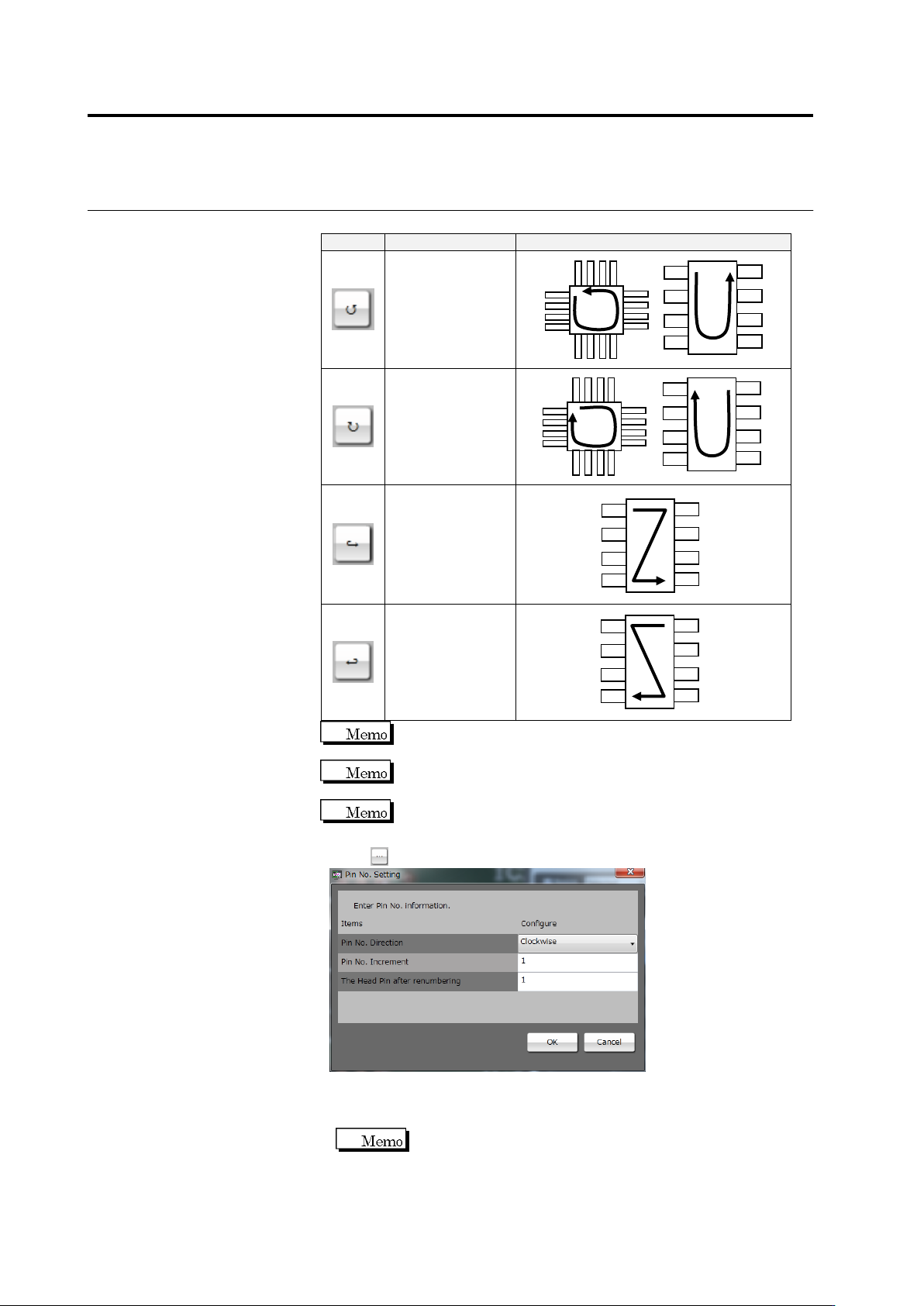
Select a pin number increment direction from the options below:
Button
Direction
Pin Numbering Example
Counterclockwise
Clockwise
From Left to Right
From Right to Left
The currently selected pin is numbered "1" in the
counterclockwise or clockwise direction.
The top left pin and top right pin are numbered "1" in the left to
right direction and right to left direction, respectively.
The left to right and right to left directions are only effective for
components such as SOPs with electrodes on both sides.
Click to change the pin numbers.
◆ Pin No. Direction: Select one of the four options above.
◆ Pin No. Increment: Enter an increment of the pin number.
◆ The Head Pin after renumbering: Enter a pin number set on pin 1.
This item can only be specified only when the pin number
direction is clockwise or counterclockwise.
Click [OK] to apply the setting.
2.4 Registering for Inspection
2-73
2.
Specify electrode information for individual electrode groups.
Select an electrode window belonging to the target electrode group.
Click to select the electrode window in the image display area, or
click the electrode in the Electrode Group List.
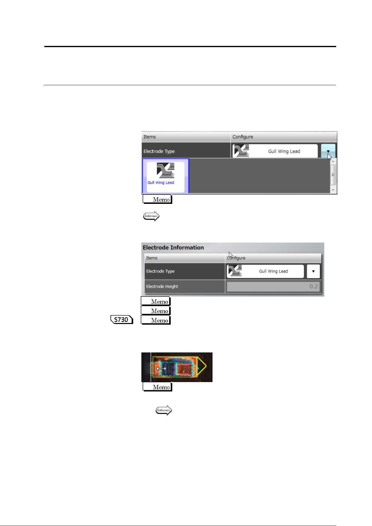
3.
Select the electrode type in the list box.
Some electrode types may not be specified depending on the
component type.
The selection of the electrode type is restricted depending on the
comonent type. Refer to "Electrode Types" for details.
4.
Specify the electrode height (Unit: mm).
The value is rounded at the 3rd decimal place.
A value in the range of 0 to 99.99 can be entered.
If automatic calculation is being selected for the component
height setup method, the electrode height is calculated
automatically while learning is performed.
5.
Specify the inflection points for a gull-wing lead.
When the positions of the inflection points are changed for any
electrode, those of other electrodes in the same group are also
changed.
Refer to "2.1.3 Image Display Area Operation" for the image
display area operation.
6.
Perform Step 1 for the remaining electrode groups, too.
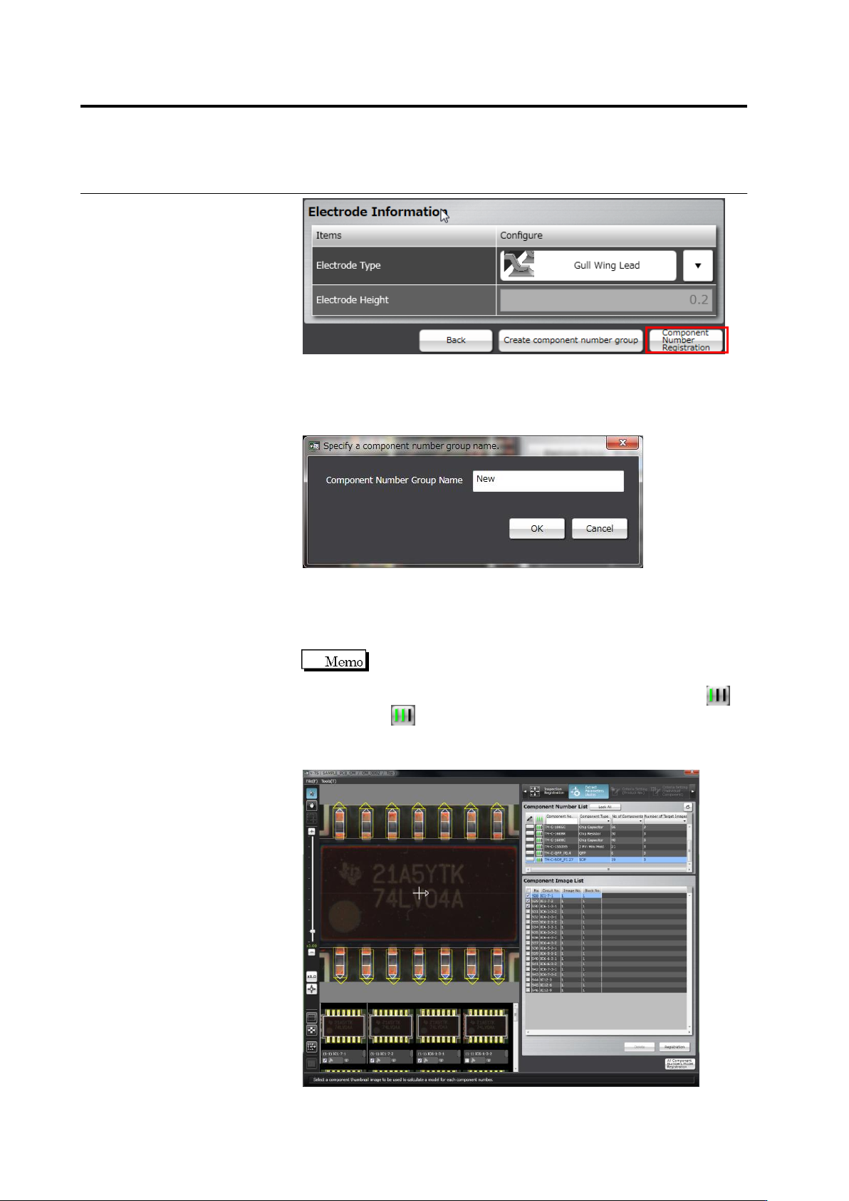
7.
Click [Component Number Registration] after all the groups are
specified with the electrode information.
Chapter 2 Inspection Programming
2-74
To create a component number group based on this component
number, click [Create component number group]. A component
number group is created simultaneously with the component number
registration. Specify a component number group name.
Go to the Component Setting screen if there are any more
component numbers to register.
Repeat the component setting to electrode setting procedures for
the components to register.
When performing component number registration, windows are
automatically pasted to all components of the same component
number, and the component number status changes from
to .
When registration for all component numbers is complete, the screen moves
to the component registration screen.