Omron V-TS Teaching Manual.pdf.pdf - 第123页
Chapter 2 Inspecti on Programm ing 2- 96 3. Select the target (PCB or Com ponent Block Unit) of adding a m ark on the PCB La yout list. Click [Add Mark] and select a m ark type in the mark list. Selectable mark types are…
2.7 PCB/Component Block Unit Setting
2-95
2.7.2 Mark Setting
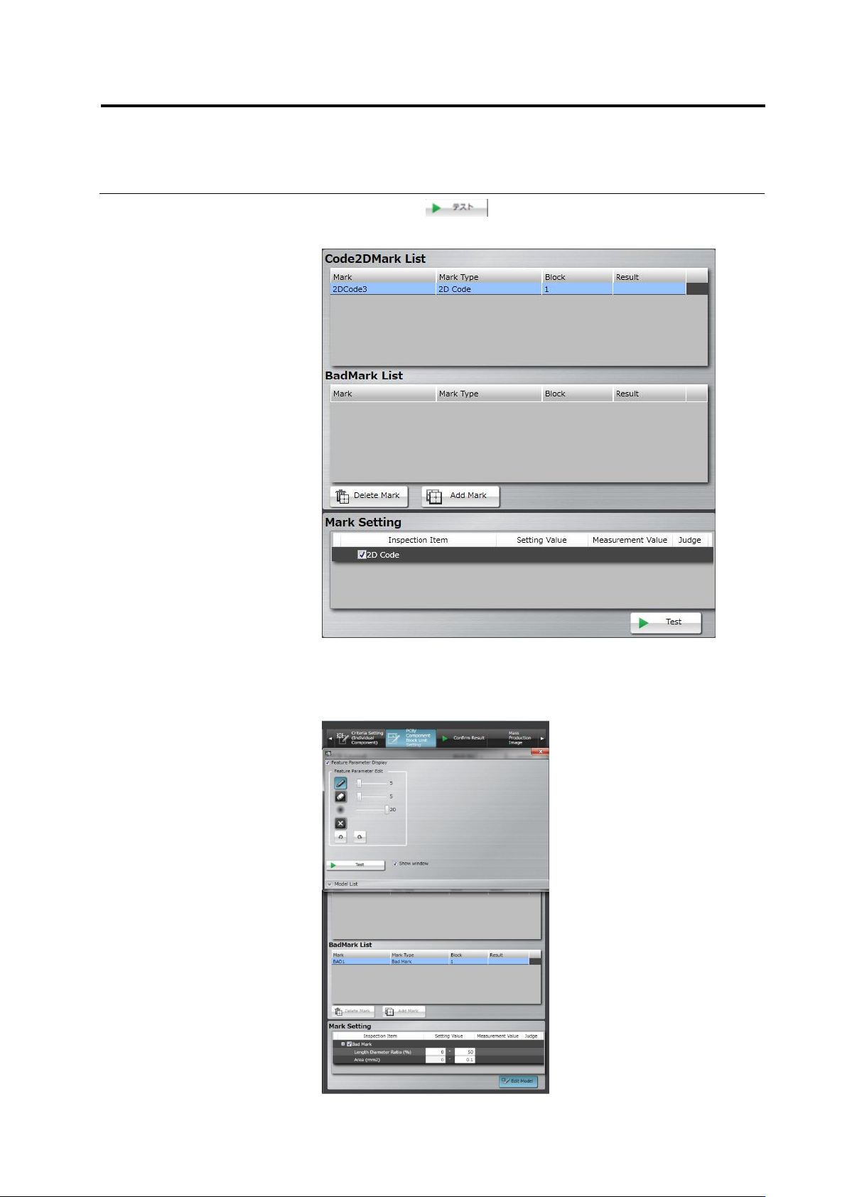
This section describes 2D code or Bad Mark setting.
Refer to the Inspection Logic Manual for the details on 2D code or Bard Mark inspection.
1.
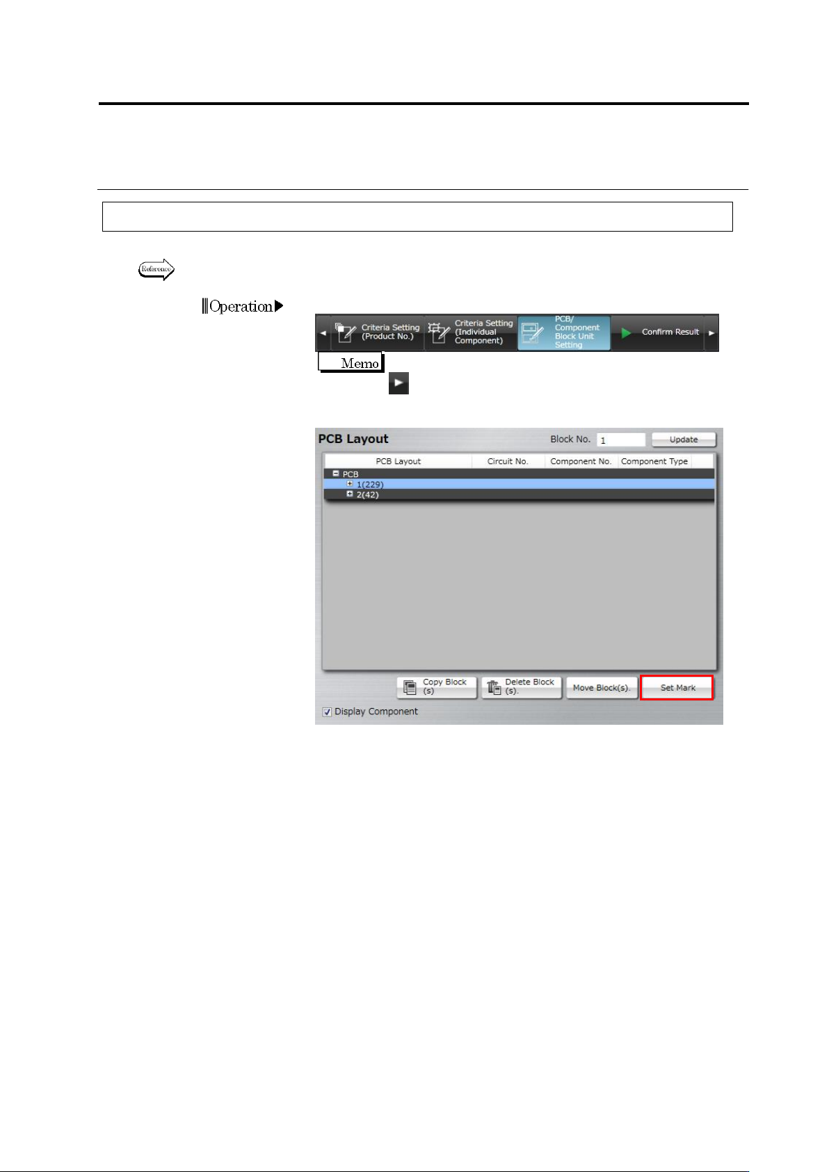
Select the [PCB/Component Block Unit Setting] tab.
If the [PCB/Component Block Unit Setting] tab is hidden, click
at the right to display it.
2.
Click [Set Mark].
Operation
Chapter 2 Inspection Programming
2-96
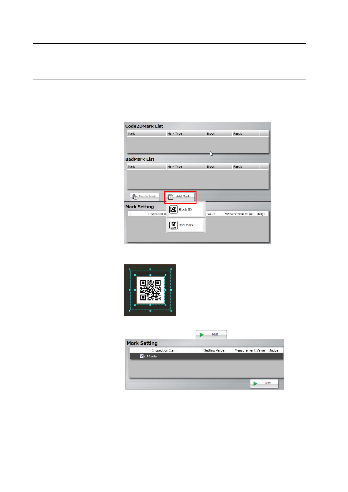
3.
Select the target (PCB or Component Block Unit) of adding a mark
on the PCB Layout list. Click [Add Mark] and select a mark type in
the mark list.
Selectable mark types are as follows:
When selecting a PCB: PCB ID
When selecting a component block unit: Block ID or Bad Mark
4.
Drag and drop the cursor to surround the mark (2D code/bad mark)
in the image display area.
5.
On the mark setting screen, select a checkbox on the inspection
item column, and click the button.