Omron V-TS Teaching Manual.pdf.pdf - 第292页
Appendix 7. Positio n Correction/Extractio n a- 15 5) Click the [Model Editing] bu tton to conf irm that the fidu cial co lor is set appropriatel y . 6) Change the color if no t appropriate.
Appendix 7. Position Correction/Extraction
a-14
Appendix 7. Position Correction/Extraction
In this section, procedures to confirm position correction/extraction, which is a misjudgment factor
common to each inspection, and repair errors.
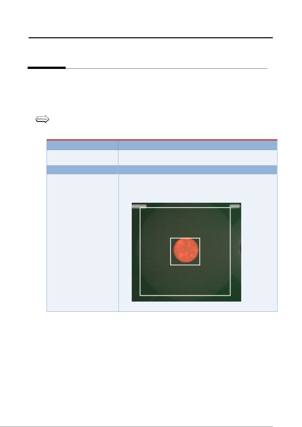
1. Fiducial correction
In the fiducial correction window, recognize PCB’s fiducial mark, and correct the camera capturing
position.
For details of fiducial correction, refer to P2-2 Section 2.2 “Fiducial Correction” of the inspection
logic manual.
Inspection result
Component image (PCB test)
N/A
N/A
Cause
Confirmation and repair method
1) Move to the “Inspection Registration” tab.
2) Click “Add Position Correction Mark” button.
3) Confirm the position and size of the fiducial window.
4) Change the position or size if not appropriate.
Appendix 7. Position Correction/Extraction
a-15
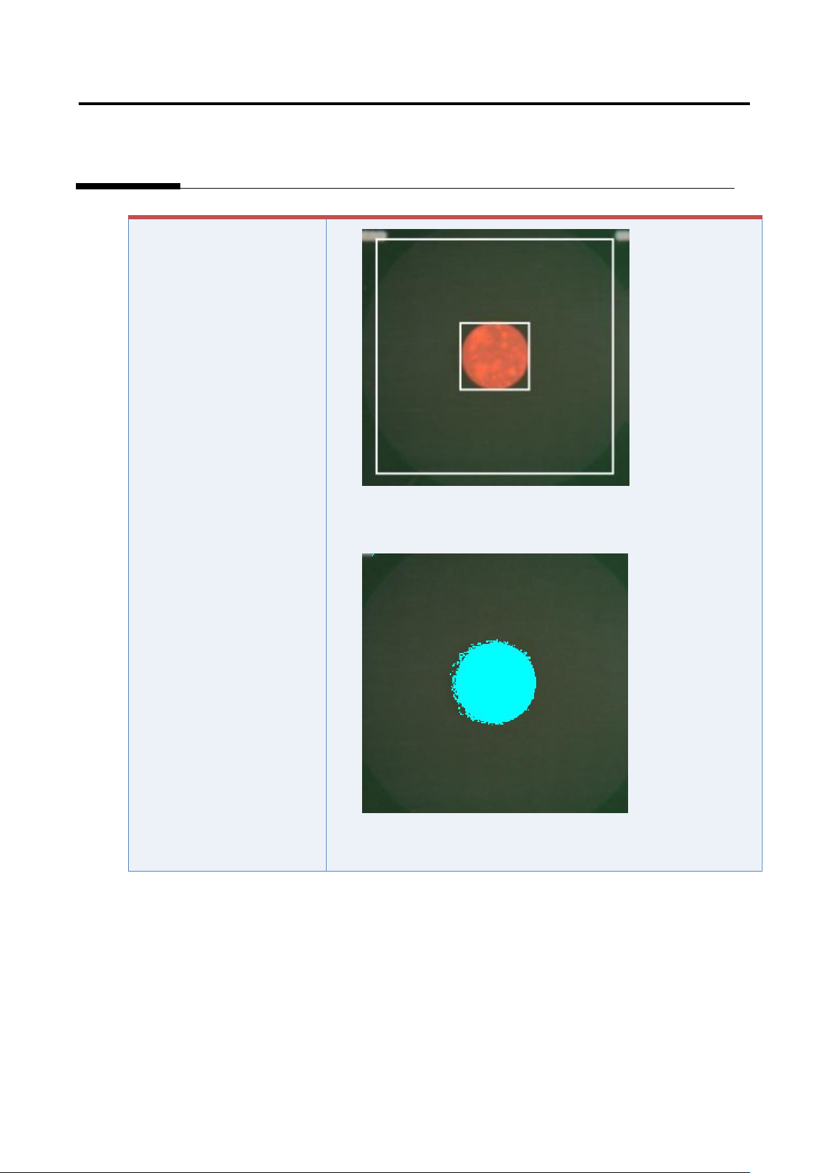
5) Click the [Model Editing] button to confirm that the fiducial color
is set appropriately.
6) Change the color if not appropriate.
Appendix 7. Position Correction/Extraction
a-16
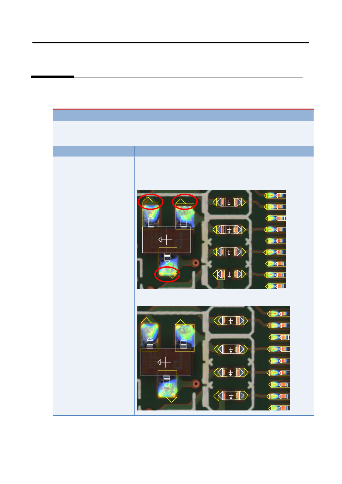
2. Inspection screen position correction
In the inspection screen, recognize the land, and correct the position of the entire captured inspection
screen.
Inspection result
Component image (PCB test)
Cause
Confirmation and repair method
The position of the land
window is not appropriate.
1) Move to the “Criteria Setting” tab.
2) Confirm that the position and size of the land window are
consistent with those of the image.
3) If not consistent, change the position or size of the land window.