Omron V-TS Teaching Manual.pdf.pdf - 第122页
2.7 PCB/Com ponent Block Unit Setting 2- 95 2.7.2 Mark Sett ing This section describes 2D code or Bad M ark s etting. Refer to the Inspection Logic Manual for the details on 2D code or Bard M a rk inspection. 1. Select t…
Chapter 2 Inspection Programming
2-94
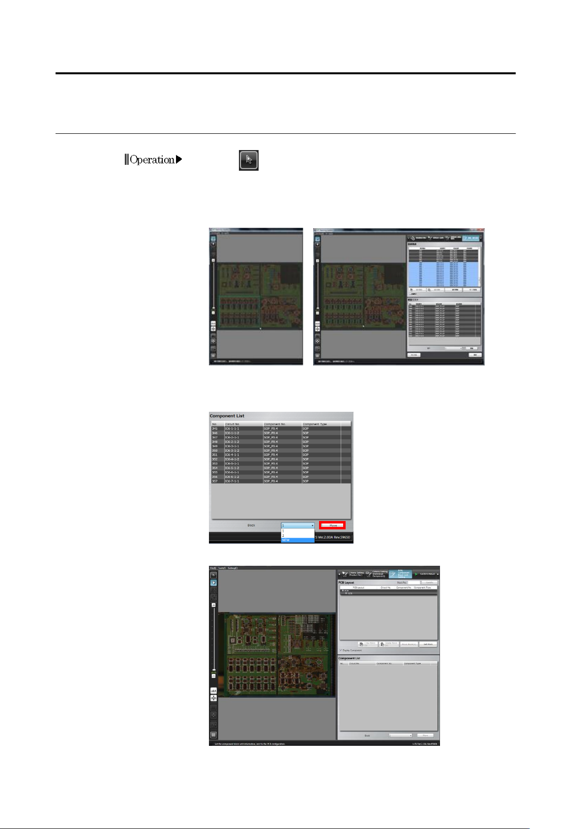
Divide a Component Block Unit
1.
Click (Select Window) button in the Image Operation tool bar.
2.
Drag to specify the range to be separated from the Component
Block Unit on the image display area. Drop the cursor. The
components included in the specified range are added to the
Component List.
3.
Select the destination Component Block Unit number the separated
portion is moved to in the list and click [Move].
To add a new component block unit number, select [NEW].
The selected component is set as another Component Block Unit.
Operation
2.7 PCB/Component Block Unit Setting
2-95
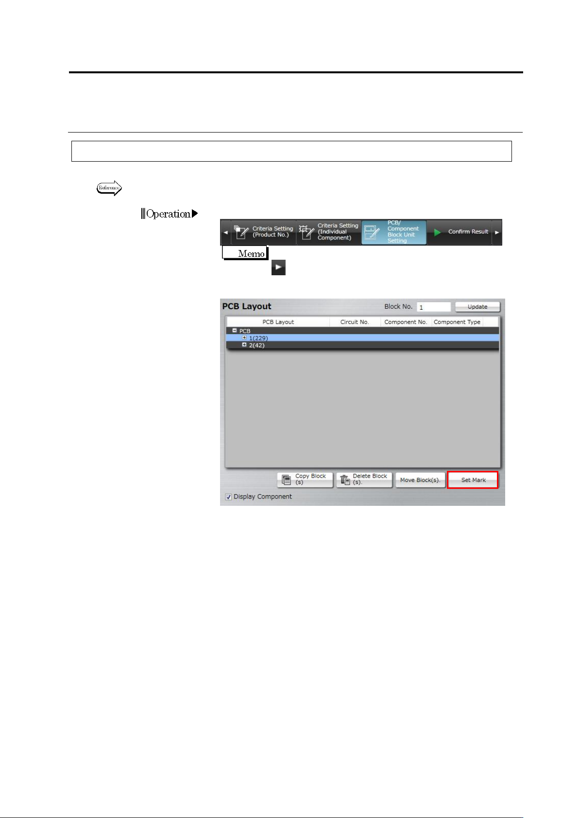
2.7.2 Mark Setting
This section describes 2D code or Bad Mark setting.
Refer to the Inspection Logic Manual for the details on 2D code or Bard Mark inspection.
1.
Select the [PCB/Component Block Unit Setting] tab.
If the [PCB/Component Block Unit Setting] tab is hidden, click
at the right to display it.
2.
Click [Set Mark].
Operation
Chapter 2 Inspection Programming
2-96
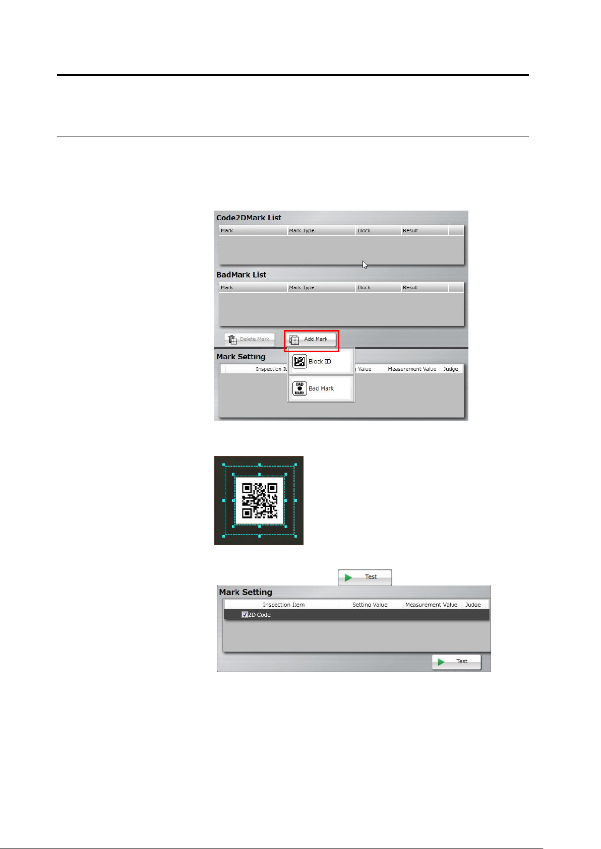
3.
Select the target (PCB or Component Block Unit) of adding a mark
on the PCB Layout list. Click [Add Mark] and select a mark type in
the mark list.
Selectable mark types are as follows:
When selecting a PCB: PCB ID
When selecting a component block unit: Block ID or Bad Mark
4.
Drag and drop the cursor to surround the mark (2D code/bad mark)
in the image display area.
5.
On the mark setting screen, select a checkbox on the inspection
item column, and click the button.