Omron V-TS Teaching Manual.pdf.pdf - 第158页
2.15 M odifying an Inspection Pr ogram 2- 131 2.15 Modifying an Insp ection Program This section explains the procedure to m odif y an inspection prog ram . 2.15.1 Modifying an Ins pection Window The size or position of …
Chapter 2 Inspection Programming
2-130
2.14 Quitting Program Editing
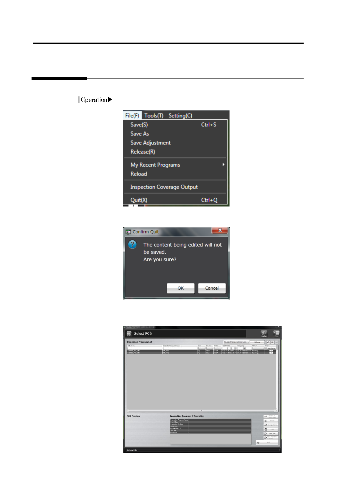
This section describes the procedure to quit Inspection Program Editing.
1.
Select [File] - [Quit] in the menu bar.
Or press [Q] while holding down the [Ctrl] key on the keyboard.
2.
The confirmation dialog appears.
Click [OK] to quit.
Click [Cancel] to return to the editing screen.
The Select PCB screen returns after exiting Inspection Program
Editing.
Operation
2.15 Modifying an Inspection Program
2-131
2.15 Modifying an Inspection Program
This section explains the procedure to modify an inspection program.
2.15.1 Modifying an Inspection Window
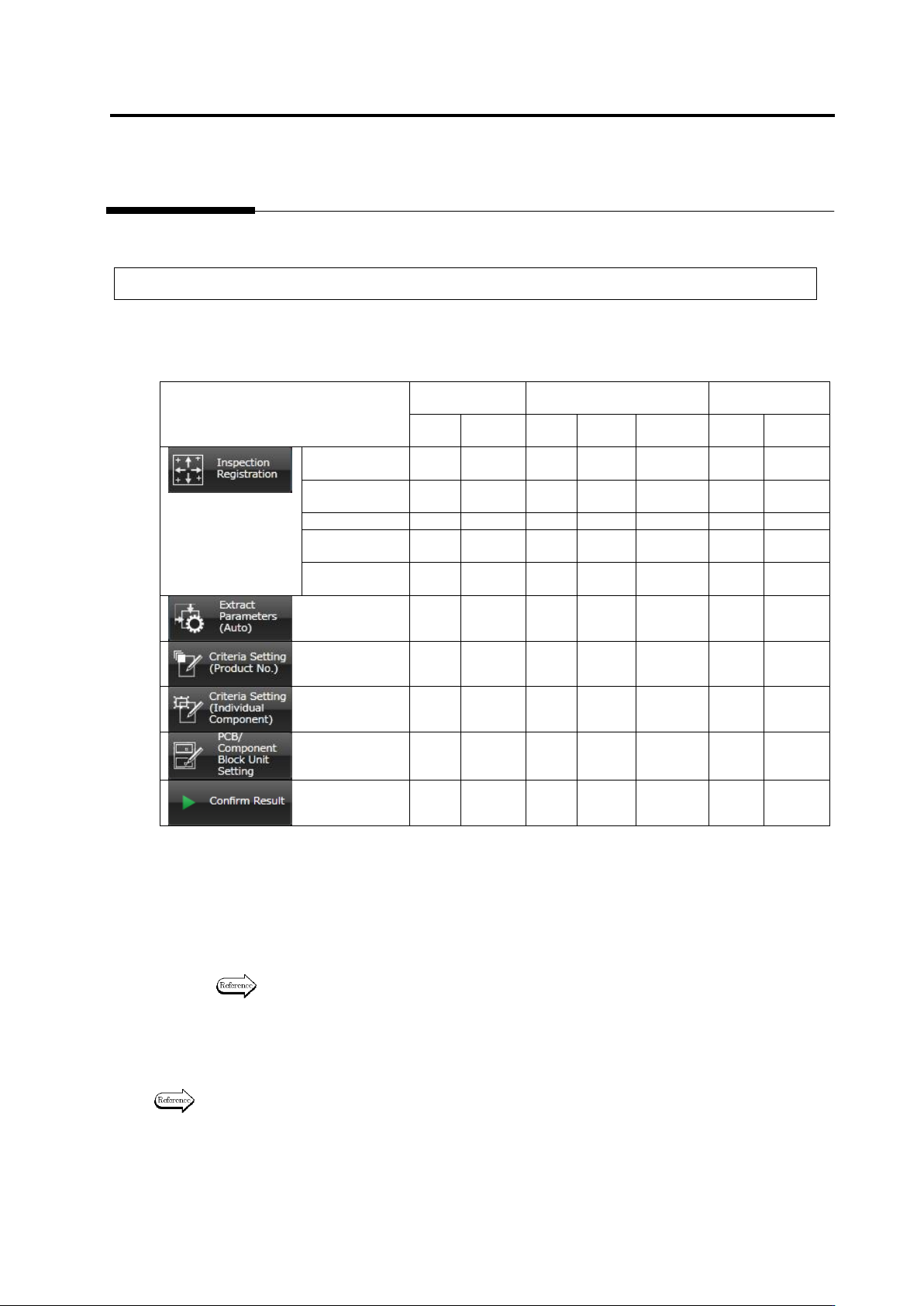
The size or position of inspection windows cannot be changed in any screen: They can only be
modified in a specific screen.
The table below shows the windows that can be modified in individual screens.
Component
Body Window
Electrode Window
Land Window
Move
Resize
Move
Resize
Inflection
Point
Move
Resize
Inspection
Registration
Yes
* 1
No
Yes
* 1
No
No
Yes
* 1
No
Component
Setting
Yes
Yes
*2
Yes
* 1
No
No
Yes
*1
No
Land Setting
No
No
No
No
No
Yes
Yes
Electrode
Group Setting
No
No
Yes
*2
Yes
*2
No
No
No
Electrode
Setting
No
No
No
No
Yes
*2
No
No
Yes
* 3
No
Yes
* 3
No
No
Yes
Yes
Yes
* 3
No
Yes
* 3
No
No
Yes
Yes
Yes
* 3
No
Yes
* 3
No
No
Yes
Yes
Yes
* 4
No
Yes
* 4
No
No
Yes
*4
No
No
No
No
No
No
No
No
Yes: Can be edited / No: Cannot be edited
*1: The component body window, electrode windows and land windows maintain their positions relative to
one another.
*2: The edited contents are reflected to all components of the same number in the inspection program (or
all components of the component number group to which the edited target belongs) at the time of
editing.
*3: The component body window and electrode windows maintain their positions relative to one another.
*4: Only moving by the unit of component block unit is possible through component block moving.
Refer to "Move a Component Block Unit" for the procedure to move a Component Block
Unit.
Click the tabs shown above to access the individual screens.
The Inspection Registration tab includes multiple screens. Click [Next] at the bottom right of the
screen to reach a desired screen.
Refer to "2.1.3 Image Display Area Operation" for the procedures to move or resize a window.
Chapter 2 Inspection Programming
2-132
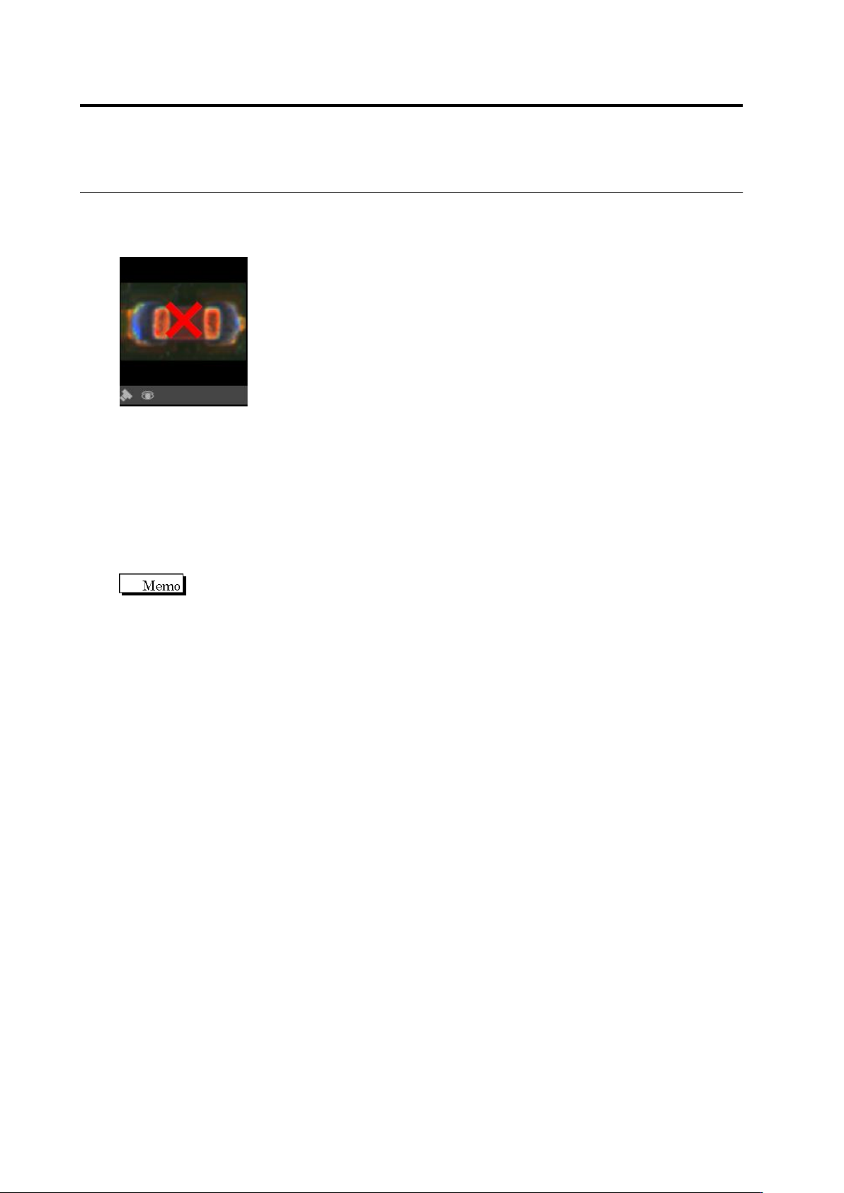
If the Component Window or Electrode Window protrudes from the model image after modifying
the Component Window size, [x] appears in the model image and the image becomes
unavailable.
When the Component Window/Electrode Window is moved back within the image, the model
image becomes available.
・ Automatic Window Position Adjustment
This function moves a Component/Electrode Window to an inspection standard position
calculated from an auto-extracted Land Window.
On the menu bar of the edit screen, select [Tool] - [Move a component to inspection standard
position].
The criteria of component offset are the window position on the inspection program screen. So,
if a component is changed or added after an inspection program is created completely, the
position of component window can be moved to the default position of the displacement
inspection criteria.