Omron V-TS Teaching Manual.pdf.pdf - 第316页
Appendix 8. Height Inform ation Setting a- 39 3. Electro de height setting pr ocedure 1 . Move to the “ Criteria Setting (Com ponent Num ber) ” tab. 2 . Select the “ Com ponent Lifting ” insp ection item , and confirm th…
Appendix 8. Height Information Setting
a-38
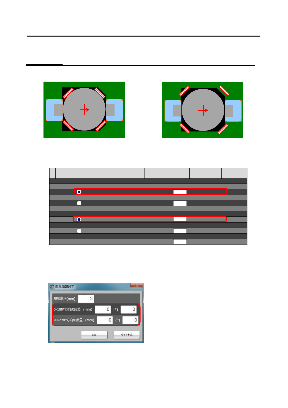
[OK sample] [NG sample]
3. After performing steps 1 and 2 appropriately, confirm the measured value of Component lifting - Tilt
- Height [absolute value] (framed in red) on the inspection criteria screen.
[Inspection Criteria Screen]
Inspection item
Setting
Measured
value
Judgment
■ Component lifting
■ Tilt (0-180°)
Height [absolute value] (mm)
0 -
[Signed] (mm)
Angle [absolute value] (°)
0 -
[Signed] (°)
■ Tile (90-270°)
Height [absolute value] (mm)
0 -
[Signed] (mm)
Angle [absolute value] (°)
0 -
[Signed] (°)
■ Lift (average height) (mm)
0 -
4. For the component tilt from which false call or overlooking occurred, fill in the area (framed in red)
of gap in the applicable direction on the component information setting screen with the measured
value of the height [absolute value] (mm) or angle [absolute value] (°) of that tilt, and conduct the
test.
5. If false call or overlooking of component tilt still remains even after the test is conducted, the setting
of lifted window might not be aligned correctly. Adjust the lifted window again to minimize the
difference of the component tilt [absolute value] which still remains as false call or overlooking
before conducting the test again.
部品傾き
(高さ
[mm]
)
部品傾き
(高さ
[mm]
)

Appendix 8. Height Information Setting
a-39
3. Electrode height setting procedure
1
.
Move to the “Criteria Setting (Component Number)” tab.
2
.
Select the “Component Lifting” inspection item, and confirm the measured value of the inspection
result of OK electrode height on the “Model Editing” screen.
3
.
Click the [Electrode Information] button at the screen bottom, and confirm the entered value of
“Electrode Height.”
4
.
If the entered value of electrode information is different from the confirmed measured value of
electrode height, change the entered value to the correctly measured value.
5
.
If false call or overlooking occurs, confirm if electrode height is measured correctly based on the
resultant electrode height on the “Model Editing” screen again, and adjust the tip extraction of the
electrode window using characteristic parameters.
Appendix 9. Land Inspection Adjustment Procedure
a-40
Appendix 9. Land Inspection Adjustment Procedure
This chapter hereafter describes causes of false call or overlooking and the procedure to confirm and
repair the fault when optimization is performed after the initial adjustment flow is executed and false call
or overlooking still remains on the wetting items of the land inspection.
For details of the wetting items of the land inspection, refer to P5-1 section 5. “Land
Inspection” of the inspection logic manual.
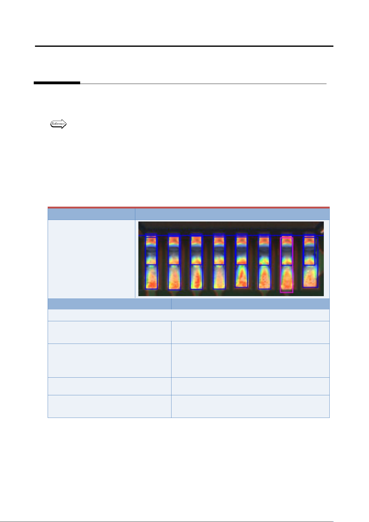
Inspection item 1. Fillet - Connection wetting angle (land wetting)
Based on the solder color detected in the land window, inspect if the land is wet with solder.
If false call or overlooking still remains in the inspection result, it is displayed as a wetting error (land
side).
The inspection result image, cause, and repair method of wetting error (land side) are as follows:
Inspection result
Image
Wetting error (land side)
Cause
Confirmation/repair method
When position does not match between the land and land window:
The land window is not positioned
appropriately.
Refer to Appendix 7.2.
The land window in the vicinity of the
applicable component is not positioned
appropriately.
Refer to Appendix 7.2.
The fiducial correction is not appropriate.
Refer to Appendix 7.1.
The position correction color is not
appropriate.
Refer to Appendix 7.2.