Omron V-TS Teaching Manual.pdf.pdf - 第66页
2.4 Registeri ng f or Insp ection 2- 39 2. Click (Create W indow) button in the Im age Operation tool bar. Drag the m ouse cursor to a corner of the PCB to surround t he adjustm ent marks. Square Mark Circular Mark Drop …
Chapter 2 Inspection Programming
2-38
2.4.1 Registering Position Adjustment Marks
Register PCB position adjustment marks. Registering them provides more precise adjustment of
inspection windows during PCB inspection.
Two PCB adjustment marks must be set. Those at the ends of a diagonal line of the PCB are
normally selected.
Refer to the Inspection Logic Manual, "2.2 Fiducial Adjustment" for the details on PCB position
adjustment.
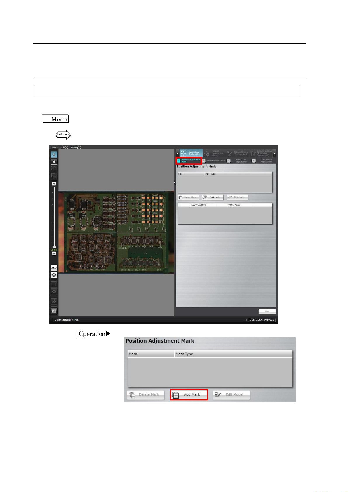
1.
Click [Add Mark].
Operation
2.4 Registering for Inspection
2-39
2.
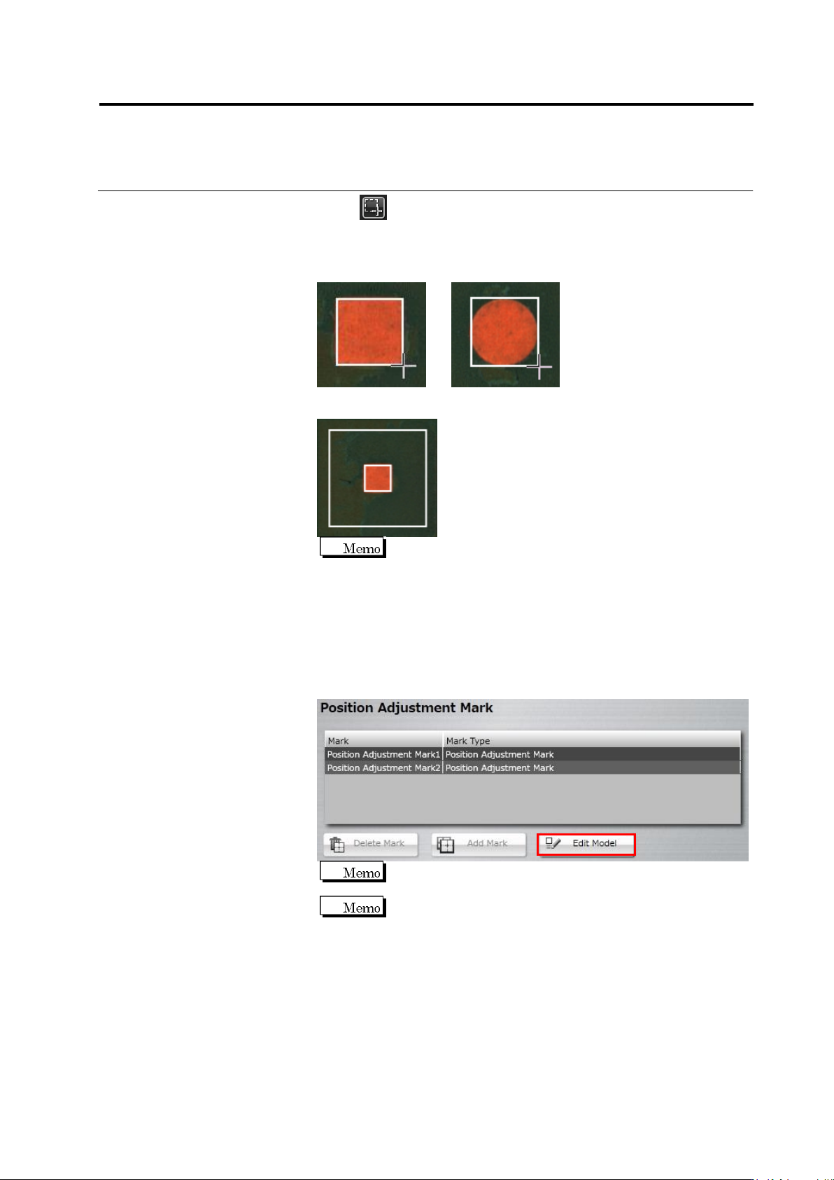
Click (Create Window) button in the Image Operation tool bar.
Drag the mouse cursor to a corner of the PCB to surround the
adjustment marks.
Square Mark Circular Mark
Drop the cursor. The mark detection area is automatically drawn.
The size of individual windows can be adjusted.
The minimum and maximum values of the outer window are as
follows:
Minimum: 2.4 x 2.4mm
Maximum: visual field’s size (different for each model)
3.
Repeat Steps 1 and 2 for the mark at the diagonally opposite corner
of the PCB.
4.
Click [Edit Model].
The [Edit Model] button becomes effective after two
adjustment marks are registered.
When you select the position adjustment mark, the [Delete
Mark] button becomes enabled.
Chapter 2 Inspection Programming
2-40
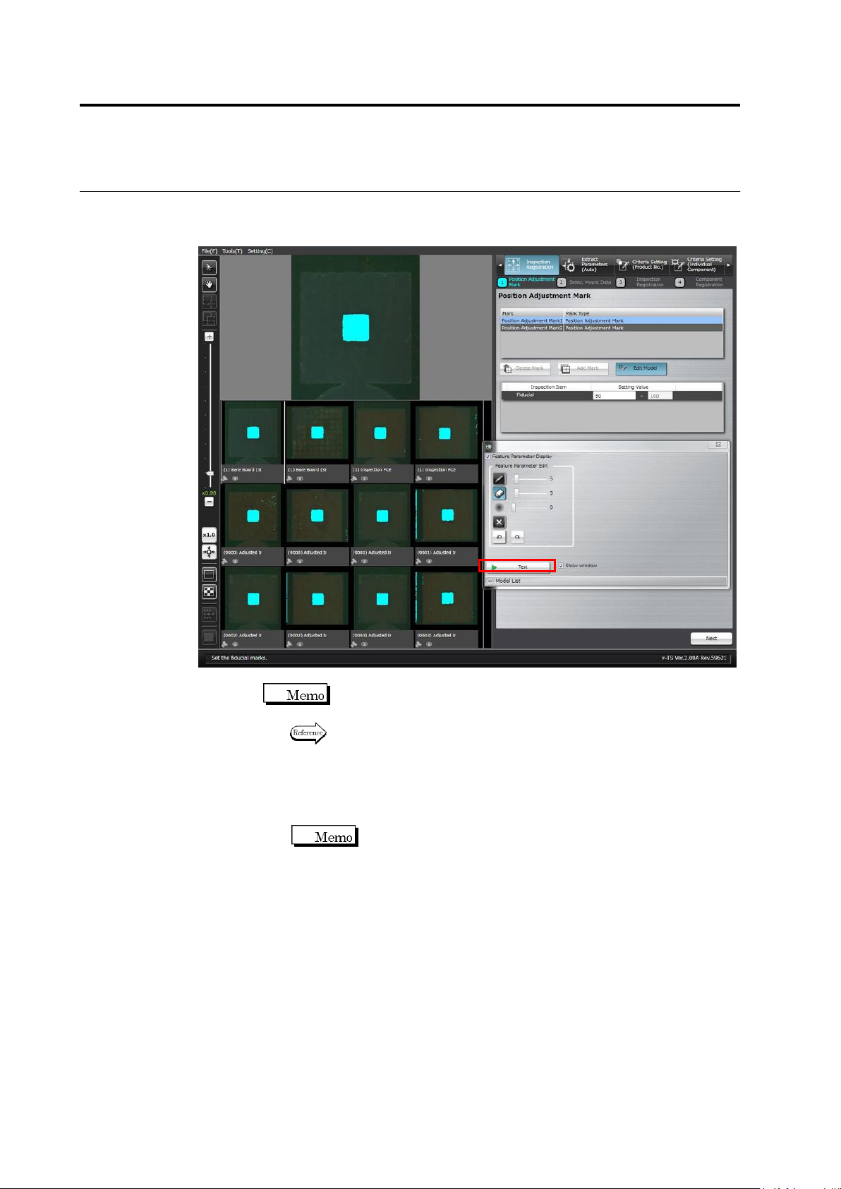
5.
The Model Editing screen is displayed.
Edit the color table to enable the detection of the adjustment marks.
Click [Test] to display the detection result in a blue window.
Position adjustment marks of other inspection PCBs or bare boards
are also displayed.
Refer to "Model Editing Screen Operation" for the details on Model
Editing screen operation.
6.
Click [Next] at the bottom right of the screen to proceed to the
Select Mount Data screen.
The [Next] button will be enabled after conducting a test.