Omron V-TS Teaching Manual.pdf.pdf - 第241页
Chapter 2 Insp ection Progr amming 2- 214 4. Enter a folder nam e and click [Save]. The fold er name can be entered w i thin 32 single -byte alphanumeric characters and the symbols shown below: ! # $ % & ' ( ) -…
2.17 Mass-Produced PCB Image
2-213
2.18.1 Saving an Inspection Program
This section describes the procedure to save an inspection program.
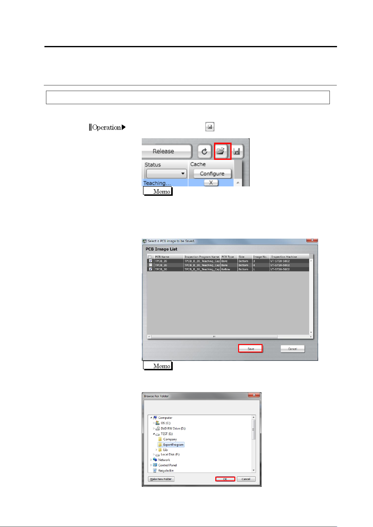
1.
Click the save button at the right above the Inspection Program
List in the Select PCB screen.
You cannot select multiple inspection programs at the same
time.
2.
The file selection dialog is displayed. Select the file to import and
click [Open]. When you also save PCB images, select the check
box of the target PCB image and click [Save]. When you do not
save PCB images, clear all the check boxes.
It takes a while to save PCB images.
3.
The folder reference dialog appears. Specify the destination and
click [OK].
Operation
Chapter 2 Inspection Programming
2-214
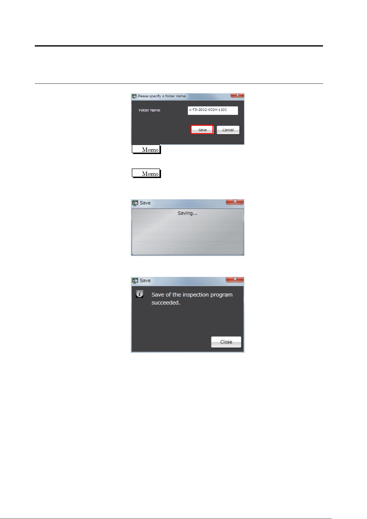
4.
Enter a folder name and click [Save].
The folder name can be entered within 32 single-byte
alphanumeric characters and the symbols shown below:
! # $ % & ' ( ) - = ^
~
@` [ { ;+ } ] ,._
␣
A folder name comprising "v-TS time/date (yyyy-mmdd-hhmm)
is displayed by default.
5.
Saving of the inspection program starts.
The following dialog is displayed if the inspection program is
successfully saved. Click [Close].
If the saving fails, an error dialog appears.
Close the dialog by clicking [Close], and check for a possible cause
e.g. the disk space or restricted access to the saving destination
folder.
2.17 Mass-Produced PCB Image
2-215
2.18.2 Reading an Inspection Program
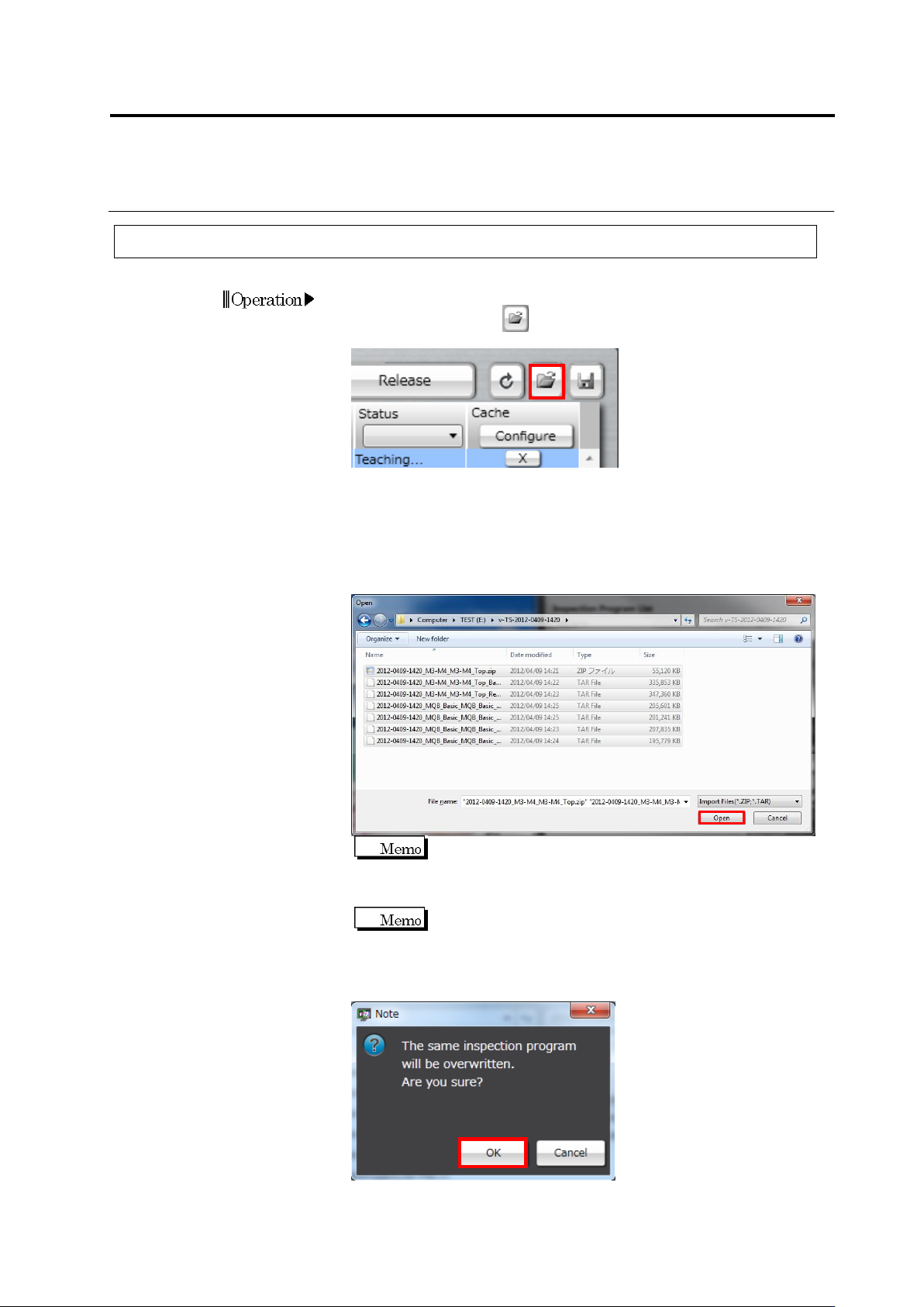
1.
To read the saved inspection program on the PCB selection screen,
click the read button at the upper right of the inspection
program list.
2.
The file selection dialog appears. Specify the saving destination of
the reading target inspection program, select the file to be read and
then click [Open].
File names in which “Bare,” “Reflow,” and “adjust” are included are
the data of a raw PCB image, an inspection PCB image, and an
adjustment image, respectively.
The ZIP format file is data excluding PCB images, and TAR
format file is data of one PCB image. When reading all the
necessary data for inspection program teaching, select a ZIP
file and TAR file for necessary images, and then click [Open].
The component ID imported is equal to the component ID
when the files are exported.
3.
The inspection program overwrite confirmation dialog appears.
Click [OK].