Omron V-TS Teaching Manual.pdf.pdf - 第175页
Chapter 2 Insp ection Progr amming 2- 148 (15) Per- pin-No. basis By checking the Per -pin-No. basis item on the m odel editing screen, inspecti on result can be displayed not onl y on a per component No. bas is but also…
2.15 Modifying an Inspection Program
2-147
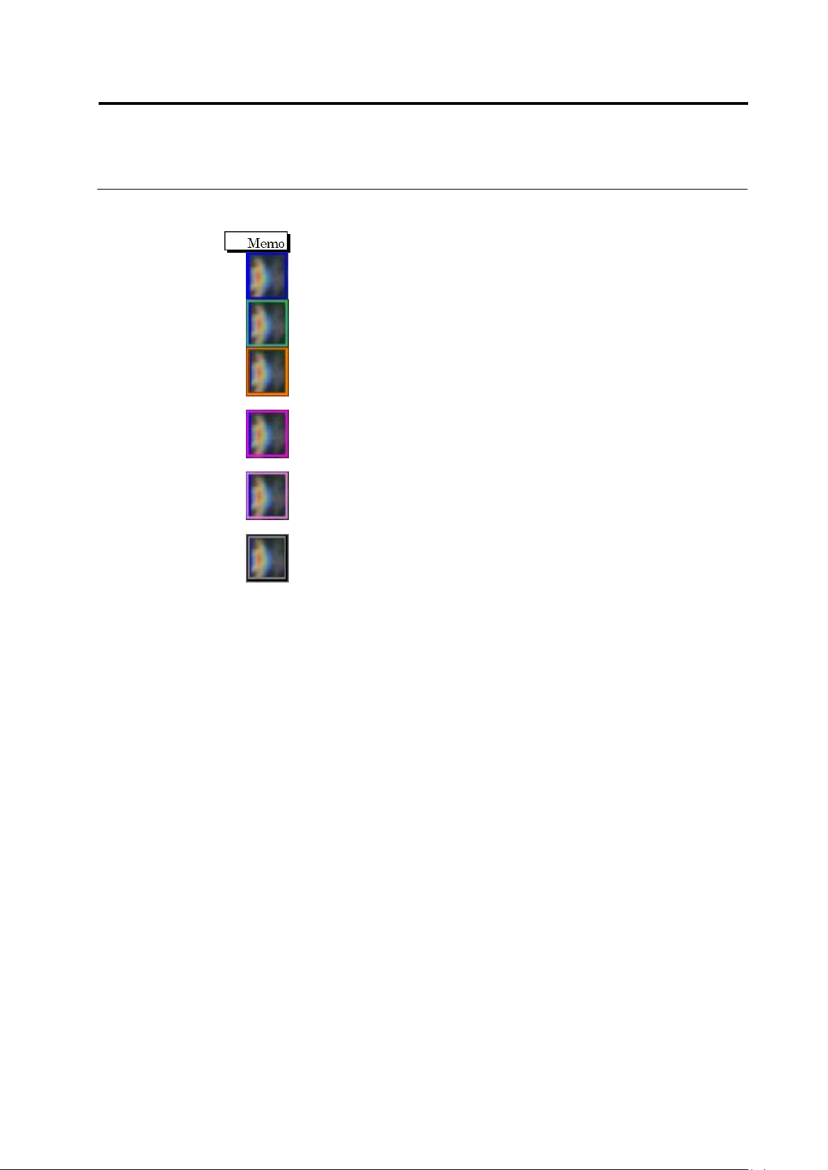
(14) Window
Displays the inspection criteria and measured value of the selected window.
The window color varies depending on the inspection result.
Blue: The inspection result is "OK".
Green: The inspection result of the specified logical expression is "OK".
Orange: The visual inspection result is not registered as fault, and the
inspection result is "NG".
Red purple: The visual inspection result is registered as fault, and the
inspection result for the selected inspection item is "NG".
Pink: The visual inspection result is registered as fault, and the inspection result
for other than the selected inspection item is "NG".
Black: The visual inspection result is registered as fault, and the inspection
result is "OK".
Chapter 2 Inspection Programming
2-148
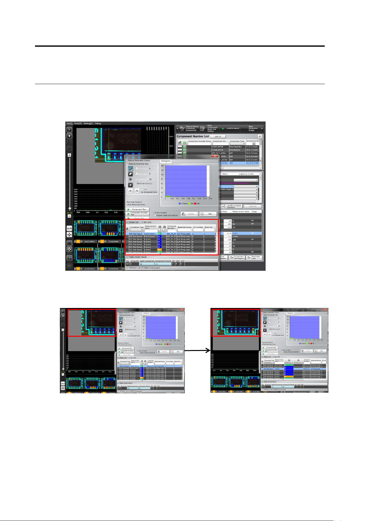
(15) Per-pin-No. basis
By checking the Per-pin-No. basis item on the model editing screen, inspection result can be
displayed not only on a per component No. basis but also on a per pin No. basis.
Model editing screen with the Per-pin-No. basis item checked
In addition, selecting a pin moves the screen so as to display the selected pin in the screen
center.
Case: Switching pin numbers from 1 to 3
2.15 Modifying an Inspection Program
2-149
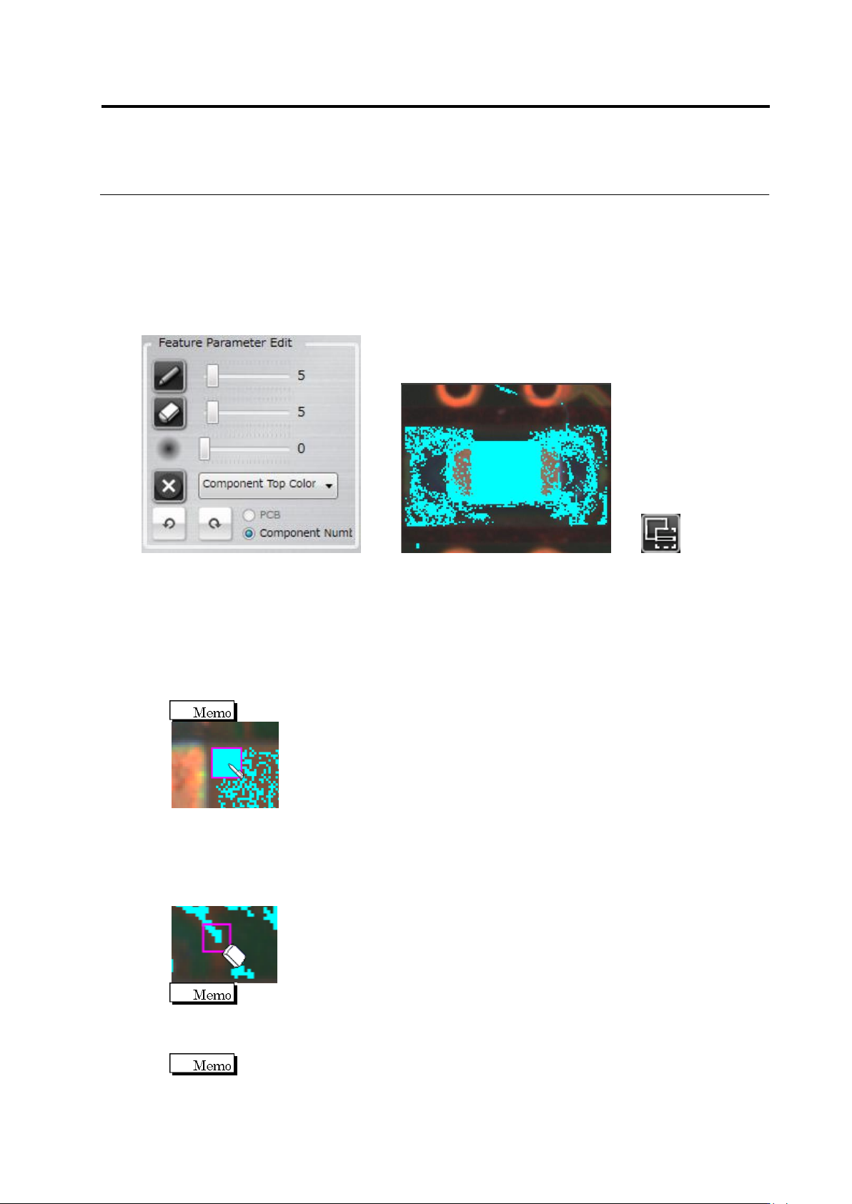
<Color Table Editing Tools>
The color table editing tools are displayed when editing characteristic parameters other than
characters or symbols.
Use the tools to add or delete colors to/from the color table after checking the extracted colors in
the component thumbnail image.
Editing Tools Component Thumbnail Image (Image in the Inspection Region Window)
(1) Displaying Characteristic Parameters
Selecting/unselecting the check box switches between presence and absence of binarized
display on the image.
(2) Pen Tool
Click the button to enable the pen tool.
Click the pixel to extract in the component thumbnail image. The color of the clicked pixel is
added to the color table. The pen size can be adjusted with the slide bar.
The pen size can be specified in the range of 1 to 41 pixels.
(3) Eraser Tool
Click the button to enable the eraser tool.
Click the extracted pixel (shown in aqua color) to erase in the component thumbnail. The
color of the clicked pixel is removed from the color table. The eraser size can be adjusted
with the slide bar.
The eraser size can be specified in the range of 1 to 41 pixels.
(4) Expansion Range Setting
Specify the expansion size of the pixel selected by the pen or eraser tool, using the slide bar.
The expansion size can be specified in the range of 0 to 20.
(1)
(2)
(3)
(4)
(5)
(6)
(8)
(7)
(9)
(10)