Omron V-TS Teaching Manual.pdf.pdf - 第108页
2.5 Registeri ng the Com ponent Num ber Model 2- 81 書 式変 更: フォ ント : ( 日 ) MS ゴ シッ ク, 1 0 pt, 文 字間 隔広 く /文 字間 隔狭 く (な し ) 削除 : Reg i s t e ri n g t h e C o m p o n e n t Num b e r Mod e l 6. Click [All Com ponent Numbers …
Chapter 2 Inspection Programming
2-80
3.
Check each component thumbnail image to determine if the image
and windows are aligned. If not, adjust the positions and sizes of
the windows.
Click a component thumbnail image or a component in the
Component Image List to select it. The field of vision on the PCB
image moves to the selected component.
Size adjustment is only possible for land windows.
The position of the Component Body Window and electrode
windows cannot be adjusted separately.
Refer to "2.1.3 Image Display Area Operation" for the image
display area operation.
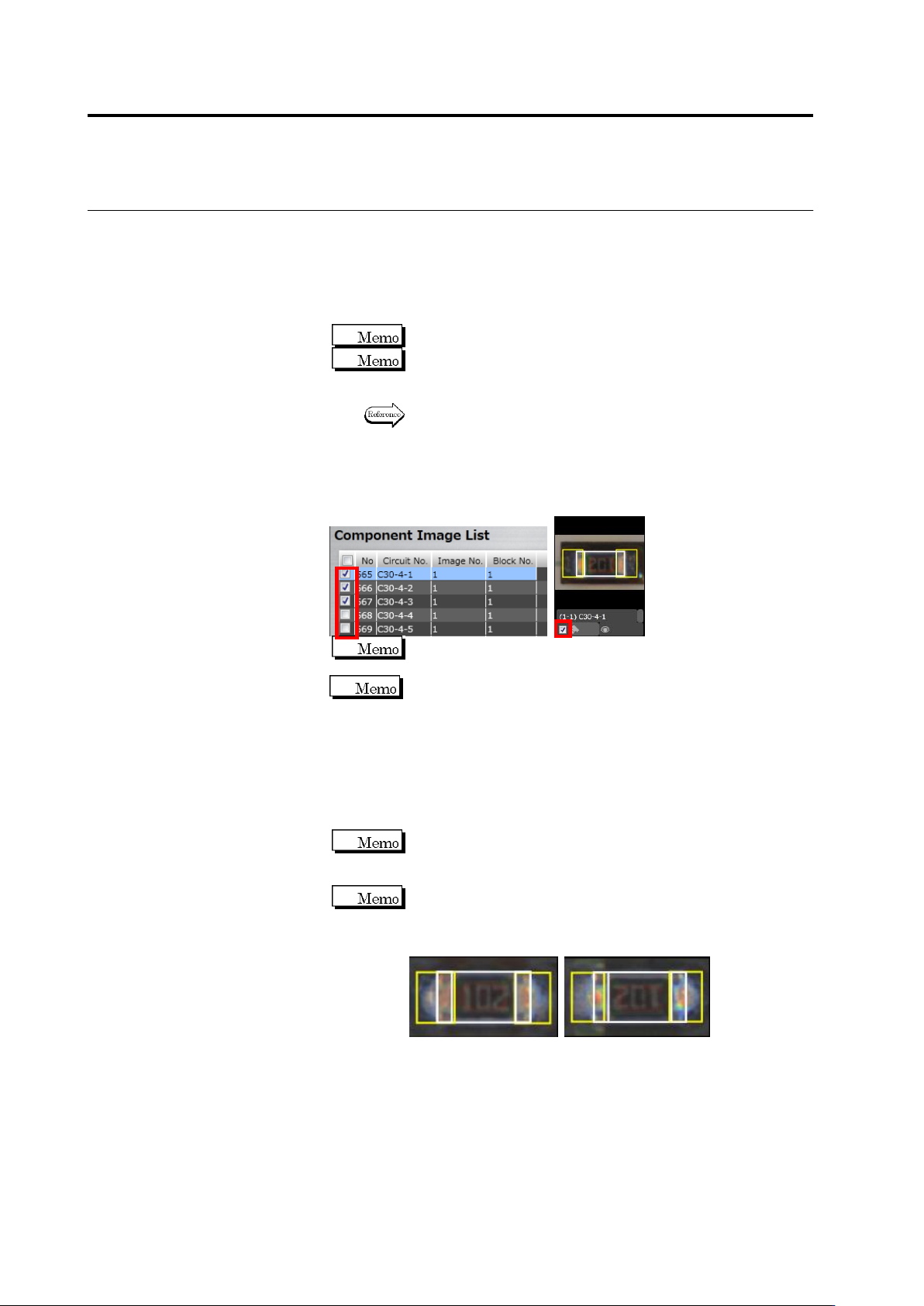
4.
Select the component thumbnail image to use for model calculation
and click the corresponding checkbox in the Component Image List
or the checkbox next to the component thumbnail image.
The checkboxes for the components selected in inspection
registration are selected by default.
It is automatically judged by the destination setting of the
component of the inspection program which captured the image
if the checkboxes on the applicable image list are checked ON
or OFF. The components not included in the destination
program are checked OFF. For the components included in the
destination program, only the images of the inspection PCB
captured by the destination program are checked ON. However,
if images are present only in the master inspection program, the
PCB images in the master inspection program are checked ON.
Multiple images can be selected. Clicking the checkbox at the
header in the Component Image List can select all the images
(checkboxes) simultaneously.
For more precise extraction of characteristic parameters,
select a good component image for the model. If there are
multiple candidates with a slight difference e.g. in the electrode
color, select them all to enhance extraction precision.
5.
Repeat Steps 2 to 4 for the component numbers with no image
specified yet.
2.5 Registering the Component Number Model
2-81
書式変更: フォント : (日) MS ゴシッ
ク, 10 pt, 文字間隔広く /文字間隔狭く
(なし)
削除: Registering the Component Numbe
r Model
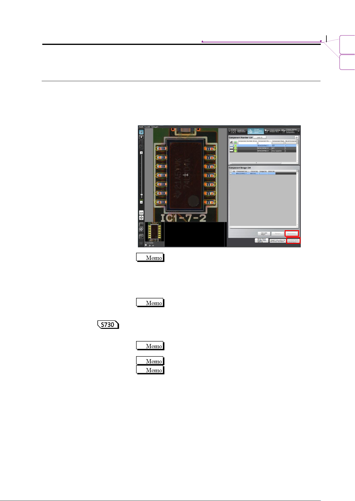
6.
Click [All Component Numbers Model Registration]. Model
calculation will be automatically performed and models will be
registered to the library.
When performing model registration for one component number
displayed on the screen, click [Registration].
When the image is not selected, the [Registration] and
[All Component Numbers Model Registration] are not
available.
7.
To learn with more model images as in mass production images,
click [Learn Again].
Pay attention that re-learning overwrites information already
configured, such as a color.
8.
To learn height again, clicking [Calculate Height] automatically
calculates the height again. To learn the height again for all
component numbers, click [Calculate Height for All Component #].
[Calculate Height] does not affect information already
configured, such as a color.
Use this function when learning height to use the 3D logic.
Perform the PCB test to calculate the height of the component
number. The median of the PCB test result is used to calculate
height.
Chapter 2 Inspection Programming
2-82
9.
By clicking the [Reference Level Model Automatic Setup] button,
the reference level model is adjusted automatically. Use this button
to reduce the manual adjustment time of editing a reference level
model when learning has not been performed yet on the existing
reference level model.
In addition, by pressing this button after learning of component
numbers is performed and settings of component block unit are
made, it is able to set the most appropriate base plane partitioning
and the base plane approximation method automatically.
For settings of component block unit, refer to Section 2.7.1
“Component Block Unit Setting.” For editing of the reference
level model, refer to Section 2.16.4 “Editing a Reference Level
Model.”