Omron V-TS Teaching Manual.pdf.pdf - 第30页
2.1 Bas ics of Teaching 2-3 2.1 Basics of Teaching This section describes the basics of teaching using v -T S. 2.1.1 Basic Knowledge of Teaching Inspection Programs A set of inspection pr ograms for individual proces s…

2-2
2.11.1 Saving an Inspection Program ............................................................ 2-118
2.11.2 Saving an Inspection Program Under a New File Name .................... 2-118
2.11.3 Releasing an Inspection Program ....................................................... 2-119
2.12 Reloading an Inspection Program ................................................................ 2-121
2.12.1 Reloading an Inspection Program Recently Used .............................. 2-121
2.12.2 Reloading Inspection Program Being Edited ...................................... 2-122
2.13 Outputting Inspection Coverage ................................................................... 2-123
2.14 Quitting Program Editing .............................................................................. 2-130
2.15 Modifying an Inspection Program ................................................................. 2-131
2.15.1 Modifying an Inspection Window ......................................................... 2-131
2.15.2 Changing Component and Electrode Information ............................... 2-133
2.15.3 Editing a Model .................................................................................... 2-135
2.15.4 Optimizing Boolean Expressions and Inspection Criterion Values ..... 2-169
2.15.5 Registering Visual Check Results ....................................................... 2-177
2.15.6 Replacing the Component Number ..................................................... 2-179
2.15.7 Changing the Component No. Name .................................................. 2-182
2.15.8 Setting up Destination ......................................................................... 2-184
2.16 Managing PCB Images .............................................................................. 2-187
2.16.1 Accessing the PCB Image Management Screen ................................ 2-187
2.16.2 Deleting a PCB Image ......................................................................... 2-189
2.16.3 Editing Models by the Unit of PCB ...................................................... 2-191
2.16.4 Editing a Reference Level Model ........................................................ 2-193
2.16.5 Changing Brightness of PCB Image ................................................... 2-205
2.16.6 Cache Setting ...................................................................................... 2-206
2.16.7 Deleting Cache .................................................................................... 2-207
2.17 Mass-Produced PCB Image ......................................................................... 2-208
2.18 Inspection Program Maintenance ................................................................. 2-212
2.18.1 Saving an Inspection Program ............................................................ 2-213
2.18.2 Reading an Inspection Program .......................................................... 2-215
2.18.3 Updating Inspection Program .............................................................. 2-217
2.18.4 Deleting an Inspection Program .......................................................... 2-218
2.18.5 Renaming an Inspection Program ....................................................... 2-219
2.18.6 Copying an Inspection Program .......................................................... 2-220
2.18.7 Outputting Content of Inspection Program List ................................... 2-221
2.18.8 Verifying Inspection Program Data ..................................................... 2-224
2.1 Basics of Teaching
2-3
2.1 Basics of Teaching
This section describes the basics of teaching using v-TS.
2.1.1 Basic Knowledge of Teaching
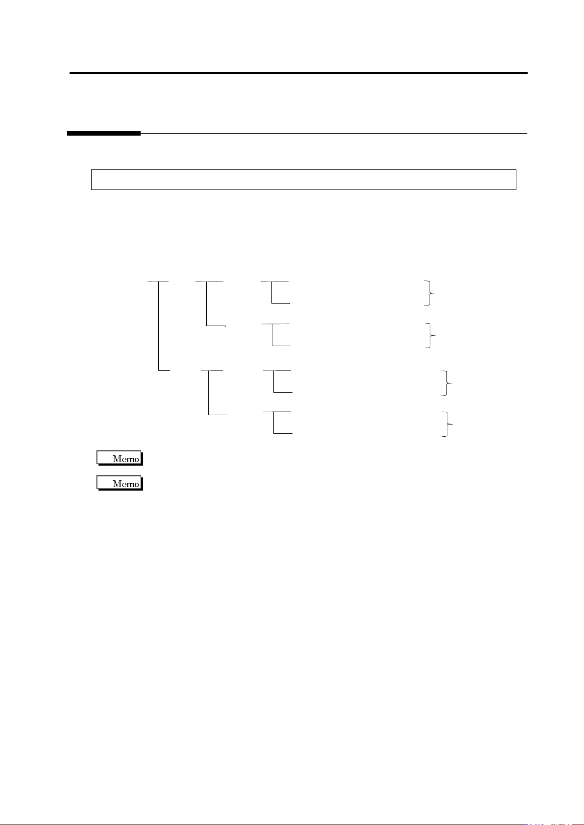
Inspection Programs
A set of inspection programs for individual processes (Z: Mount, and S: Reflow), PCB surfaces
(top or bottom) and destinations are required.
PCB Name:
AAA
Top
Bottom
Inspection Program: Z_TOP_0001
Destination
Mount
Process
Reflow
Process
Inspection Program: Z_TOP_0002
Inspection Program: Z_BOTTOM_0001
Mount
Process
Reflow
Process
Inspection Program: Z_BOTTOM_0002
Inspection Program: S_TOP_0001
Destination
Inspection Program: S_TOP_0002
Inspection Program: S_BOTTOM_0001
Inspection Program: S_BOTTOM_0002
Destination
Destination
v-TS only supports the creation of inspection programs for the implementation and reflow
processes.
"Destination" here refers to the variations of PCBs including different components or component
numbers, which go through the same printing process. Due to the difference of mounting
configuration, different inspection programs are required and teaching must be performed
separately.
To set up destination, refer to Section 2.15.8 “Setting up Destination.”
Chapter 2 Inspection Programming
2-4
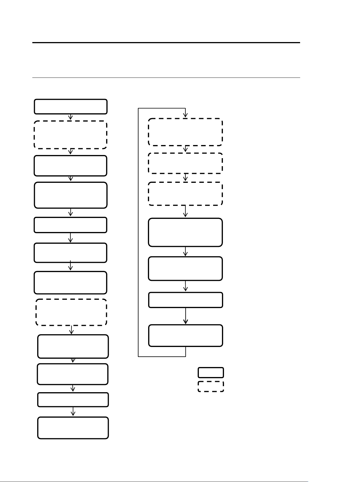
Teaching Flow
1) New creation
Shoot raw PCBs and
inspection PCBs using
the PCB inspection
system
4) Set up the criterion
5) Set up PCB and
component block ID
2) Register inspection
Set up destination
3) Register the
component number
model
■ Inspection program creation flow
14) Release the
inspection program
Inspect the PCB using
the PCB inspection
system
Classify OK and NG
products using v-CA
Monitor and analyze the
result using Q-upNavi
12) Correct the
inspection program
13) Confirm the result
■ Inspection program tuning flow
v-TS
Other than v-TS
6) Adjust and save the
inspection program
10) Release the
inspection program
7) Confirm the PCB
test result
9) Confirm the result
Inspect the PCB in
adjustment mode using
the PCB inspection
system
8) Correct the
inspection program
11) Confirm inspection
NG images captured
during mass-production