Omron V-TS Teaching Manual.pdf.pdf - 第192页
2.15 M odifying an Inspection Pr ogram 2- 165 <Lifted Component Inspe ction Edit ing Tool s> If the com ponent height/lifted component inspect ion is being se lected, the lifted c omponent inspection editing t ools…
Chapter 2 Inspection Programming
2-164
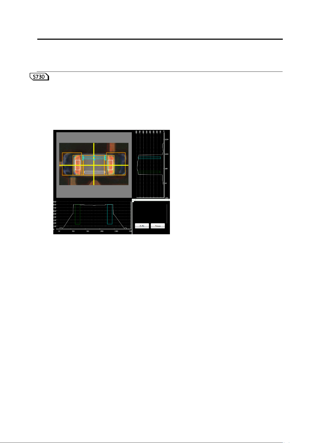
(7) Lifted Component Window
A window to inspect component height and lifted component is displayed on the X-Y diagram
as a white frame.
A lifted component window area is displayed in the X-Z and Y-Z diagrams.
When an incline of 0-180° or 90-270° is selected, the yellow and light blue frames indicate
the reference point and measurement point, respectively. If neither range is selected, the
window is displayed in gray.
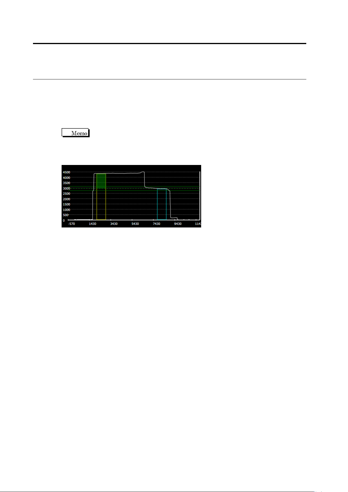
To the yellow frame of the reference point, the height of the preset unevenness
is displayed as a green paint-out frame. The green reference point is displayed in the
position which is the height of the unevenness above the top of the yellow frame of the
reference point. The green dotted line indicates the center of the reference, and the green
solid line indicates the upper and lower limits of the inspection settings, respectively.
2.15 Modifying an Inspection Program
2-165
<Lifted Component Inspection Editing Tools>
If the component height/lifted component inspection is being selected, the lifted component
inspection editing tools are displayed.
If the component height or lifted component (average height) is being selected, the lifted
component window is displayed in a white frame on top of the component. Inspect component
height/lifting by editing the position and/or size of the lifted component window.
(1)
Chapter 2 Inspection Programming
2-166
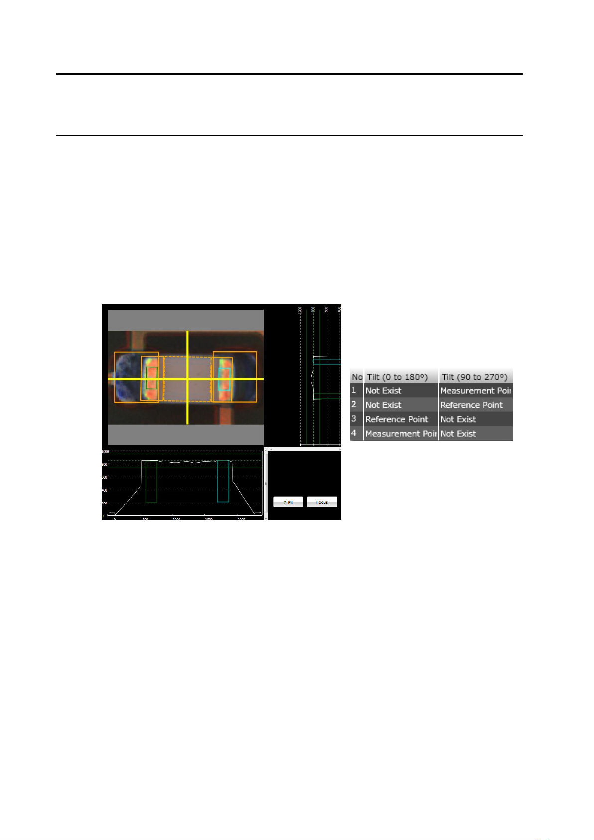
(1) Lifted Component Window
Specify a measurement range of height information used for the component height/lifted
component inspection. Use the mouse to edit the window position and size.
If the component tilt (0-180)/(90-270) is being selected, the lifted component window is
discriminated to reference point and measurement point. Described below are details.
Reference Point: Indicates a region as a height reference to measure the component tilt
(framed in yellow).
Measurement Point: Indicates a region to calculate a height from the reference point to
measure the component tilt (framed in light blue).
To change the reference point/measurement point setting, use the lifted component window
list.