Omron V-TS Teaching Manual.pdf.pdf - 第308页
Appendix 7. Positio n Correction/Extractio n a- 31 7. Electrode Tip Extractio n Inspection result Component im age (PCB test) Cause Confirm ation and repair method Electrode tip ex traction is not aligned. 1) Move to the…
Appendix 7. Position Correction/Extraction
a-30
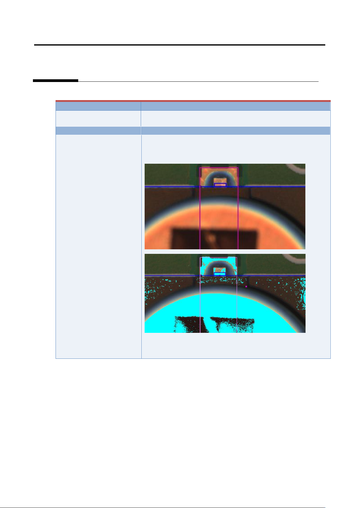
6. Electrode side extraction
Inspection result
Component image (PCB test)
Cause
Confirmation and repair method
Electrode side extraction is
not aligned.
1) Move to the “Criteria Setting” tab.
2) Select “Inspection Criteria” - “Electrode Side Extraction,” and
click the [Model Editing] button.
3) Confirm if the electrode color is being set.
4) Set the electrode color if not being set.
Appendix 7. Position Correction/Extraction
a-31
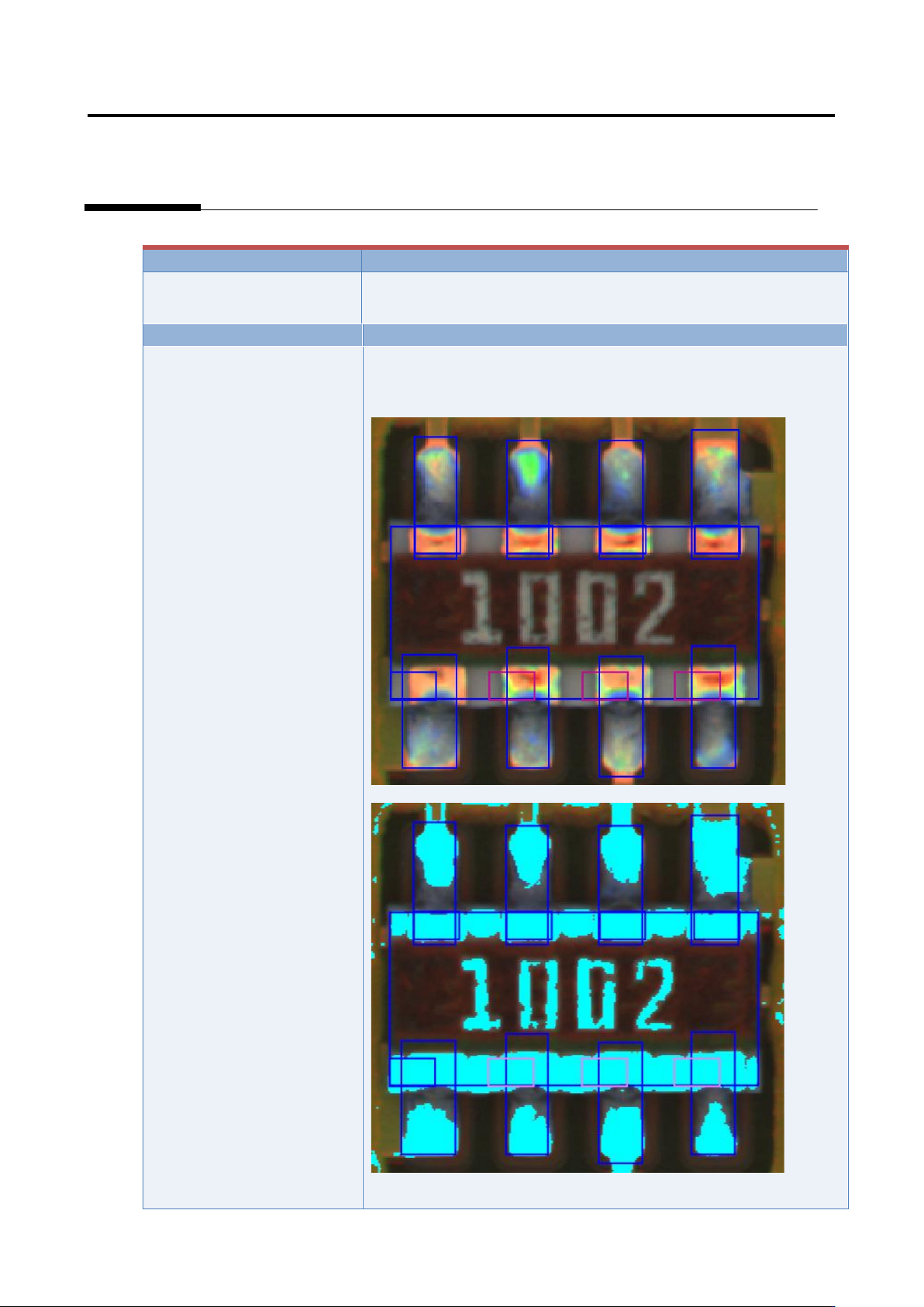
7. Electrode Tip Extraction
Inspection result
Component image (PCB test)
Cause
Confirmation and repair method
Electrode tip extraction is not
aligned.
1) Move to the “Criteria Setting” tab.
2) Select “Inspection Criteria” - “Electrode Tip Extraction,” and
click the [Model Editing] button.
3) Confirm if the electrode color is being set.
4) Set the electrode color if not being set.
(*Image to be pasted)
Appendix 7. Position Correction/Extraction
a-32
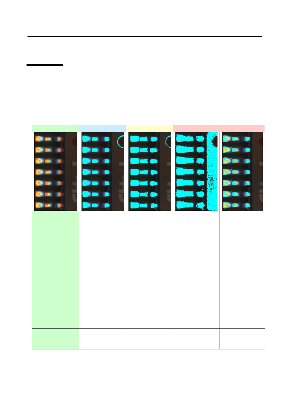
Details of the procedure to adjust electrode tip extraction using characteristic parameters are as follows:
Electrode tip extraction succeeds if the following two conditions are satisfied.
(1) Electrode binarization ... The electrode is binarized with the electrode color.
(2) Solder binarization ... The solder close to the electrode is not binarized with the electrode color.
Example 1.
Capture image
Good
Acceptable
Unacceptable
(1) Electrode
binarization
○
○
○
×
Electrode tip
extraction fails
because the
electrode is not
binarized.
(2) Solder
binarization
○
△
Electrode tip
extraction may fail
in the future
because the
electrode and
solder are partly
connected.
×
Electrode tip
extraction fails
because the
electrode and
solder are
connected.
○
Availability of
electrode tip
extraction
○
○
×
×