Omron V-TS Teaching Manual.pdf.pdf - 第81页
Chapter 2 Inspecti on Programm ing 2- 54 2. Select the com ponent type in the list box . Refer to "2.1.1 Basic Knowledge of Teaching", "Component Types " for the types of components. W hen a chip resi…
2.4 Registering for Inspection
2-53
2.4.5 Component Registration
Position the Component Body Window, land windows and electrode windows on a sample
component of individual component numbers and set the component and electrode information
for them.
2.4.5.1 Component Setting
Set the component information for each component number.
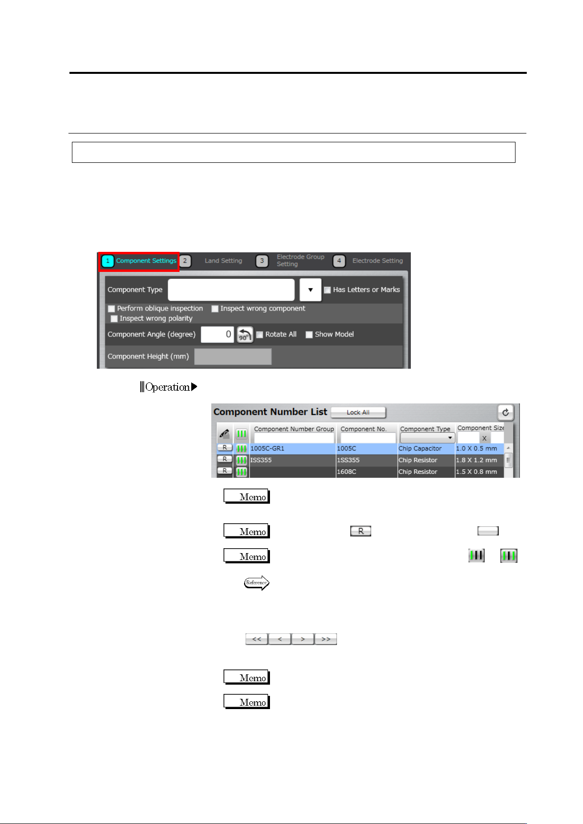
1.
Select the component number for the setting in the Component
Number List.
If the component number is registered in the library and the
component information obtained from the library is used, this
setting is not necessary.
When the status is (locked), click it to unlock (not
locked) the component number.
If the teaching status of the component number is or ,
perform automatic window adjustment.
Refer to (5) Information Display Area on “2.1.2 Configuration of
the Editing Screen” for details on the status display of the
component number and auto adjustment procedure.
If there are multiple components with the same component number,
click below the Component Number List to
switch the component displayed in the image display area. Select
the sample component.
Click [<<] to display the top component and [>>], the last
component.
Select a component image rendered in clear colors, without
noise such as shadow, as the sample component, which can
enhance the accuracy of auto component window positioning
for the same component number.
Operation
Chapter 2 Inspection Programming
2-54
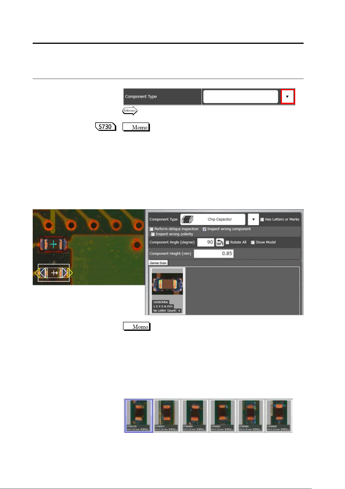
2.
Select the component type in the list box.
Refer to "2.1.1 Basic Knowledge of Teaching", "Component Types"
for the types of components.
When a chip resistor, chip capacitor, or other chip/ melf/
component type is selected, the component body window is set up
automatically. If you do not wish this window to be set up
automatically, select [Setting] - [Application Settings] - [Component
Window Setting Method] -> [Manual Settings] on the menu bar.
3.
Find groups with the same shape and same color in the component
number group list.
When setting the “Same size” toggle button ON, if you found an
appropriate component number group, click the thumbnail and
select [Add], then go to step 9.
If you couldn't, go to step 4.
Component number groups are configured based on the
following guideline.
- Components with the same shape/size/electrode count shall
belong to the same group.
- A group shall be configured for each color, e.g. white, black, and
brown based on the visual check.
- A group shall be configured for each component color if there are
multiple component colors.
(e.g.) Configuring a group of chip resistor (black) with the same
shape and size.
2.4 Registering for Inspection
2-55
(e.g.) Configuring a group of chip capacitor (white/gray) with the
same shape and size.
Move the mouse cursor on the component number
group thumbnail, the component number group preview window
appears on the image. When a component number is added to the
component number group, the setting of the component number is
synchronized with the component number group. While creating a
new component number group, saving/loading an inspection
program before component registration (automatic) shows a dark
preview image. After performing component registration (automatic),
the image appears.
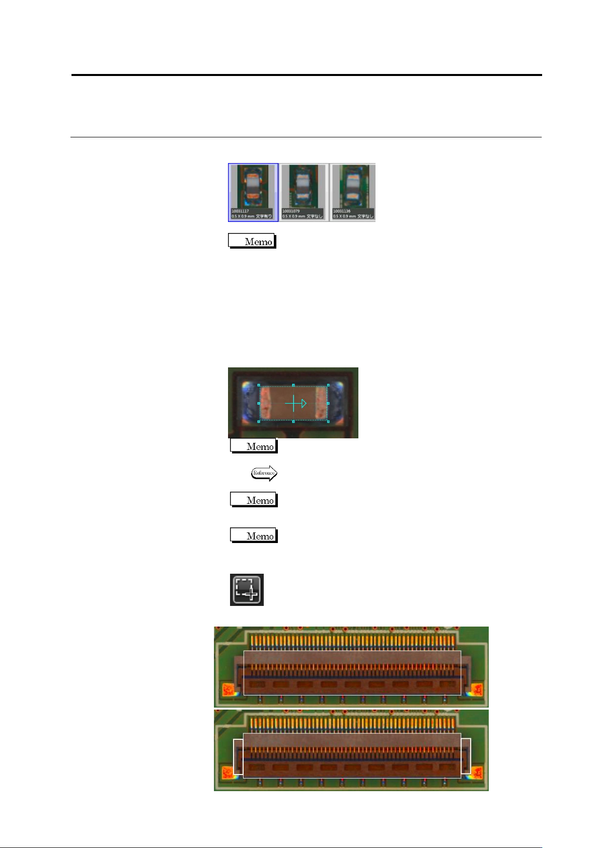
4.
Draw a Component Body Window in the image display area.
Magnify the display area to draw a window for more precise
window positioning.
Refer to "2.1.3 Image Display Area Operation" for the image
display area operation.
The "+" mark moves to the center of the window after the
component window is formed.
If you cannot configure a component outline shape using a
rectangular frame for an odd-shaped component after
configuring the component body window, add a window to
complement the component body window.
Create Window Button
If a component outline is out of the component body window, add a plus
window.