Omron V-TS Teaching Manual.pdf.pdf - 第118页
2.7 PCB/Com ponent Block Unit Setting 2- 91 2.7 PCB/Component Block Unit Setting 2.7.1 Component Bl ock Unit Setting This section describes the copying, de leting, moving and d ividing of a Com ponent Block Unit. Open …
Chapter 2 Inspection Programming
2-90
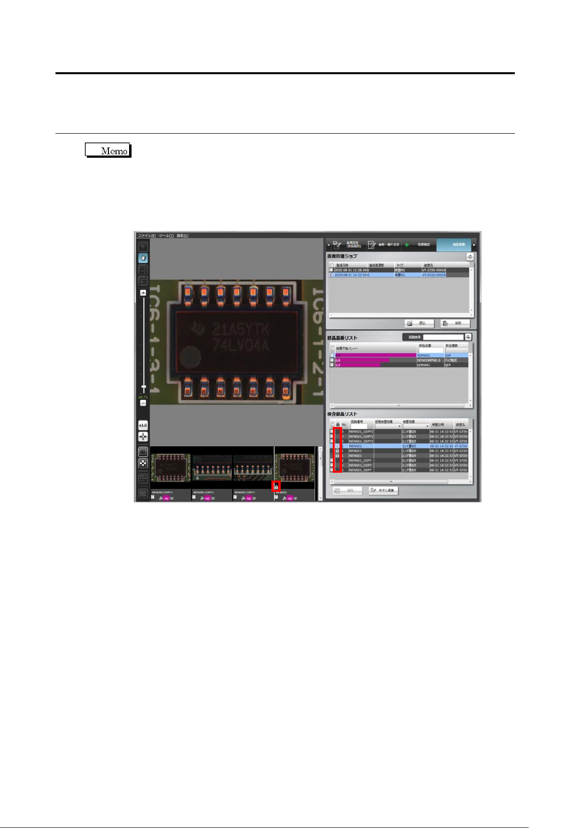
When the circuit of the mass production image (not registered) on the mass production
image registration screen, an icon for individual setting is displayed on the list.
For this, mass production images (not registered) in which individual setting is applied
can be judged with the simulation for mass production images. The circuit in which
individual inspection criteria are configured as shown below is displayed as individual
icons on the inspection component list and thumbnail screen.
2.7 PCB/Component Block Unit Setting
2-91
2.7 PCB/Component Block Unit Setting
2.7.1 Component Block Unit Setting
This section describes the copying, deleting, moving and dividing of a Component Block Unit.
Open the Component Block Unit Setting Screen
1.
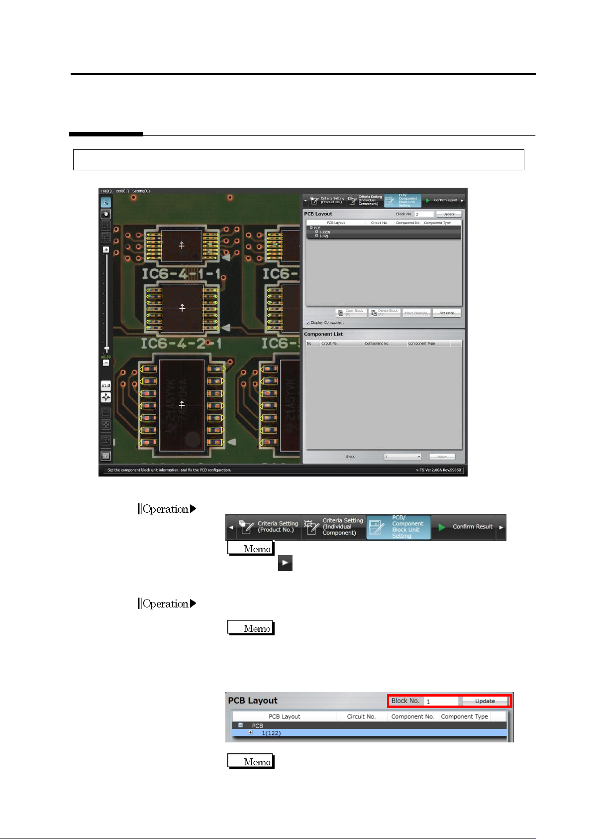
Click to select the [PCB/Component Block Unit Setting] tab.
If the [PCB/Component Block Unit Setting] tab is hidden, click
at the right to display it.
Edit a Component Block Unit Number
1.
Click to select the target Component Block Unit in the PCB Layout
list.
Find the corresponding "Component Block Unit No. (The
number of components)" in the PCB Layout column.
2.
Enter a new Component Block Unit number and click [Update].
The Component Block Unit number is changed and the PCB Layout
display is updated.
A Component Block Unit number can be entered within 16
alphanumeric characters (Symbols cannot be used).
Operation
Operation

Chapter 2 Inspection Programming
2-92
Copy a Component Block Unit
1.
Click to select the original Component Block Unit to copy in the
PCB Layout list.
Find the corresponding "Component Block Unit No. (The
number of components)" in the PCB Layout column.
2.
Click [Copy Block(s)].
3.
Specify the number of component block units to create and click
[Adjust]. Component block units for XY position adjustment are
displayed for vertical and horizontal directions. To copy a
component block unit only in the vertical direction, enter "1" for the
horizontal direction.
4.
Align the window positions of component block units for position
adjustment to the component block units at the end of the
vertical/horizontal directions.
5.
Clicking [Preview] displays component block unit windows at even
intervals calculated based on the number of component block units
and positions of the component block units for position adjustment.
[Preview] is enabled by clicking [Adjustment].
6.
Click [OK] to copy a component block unit.
7.
You can independently adjust a position of the copied component
block unit as necessary.
Refer to the next page for the procedure to move the Component
Block Unit.
Delete a Component Block Unit
1.
Click to select the Component Block Unit to delete in the PCB
Layout list.
2.
Click [Delete Block(s)].
The [Delete Block(s)] button is disabled when only one
Component Block Unit is listed.
Operation
Operation