Omron V-TS Teaching Manual.pdf.pdf - 第37页
Chapter 2 Inspection Programm ing 2- 10 2.1.2 Configuratio n of the Editing S creen The screenshot belo w shows the configurati on of the Inspection Pr ogram Editing s cr een. To view the editing sc reen, select a PCB yo…
2.1 Basics of Teaching
2-9
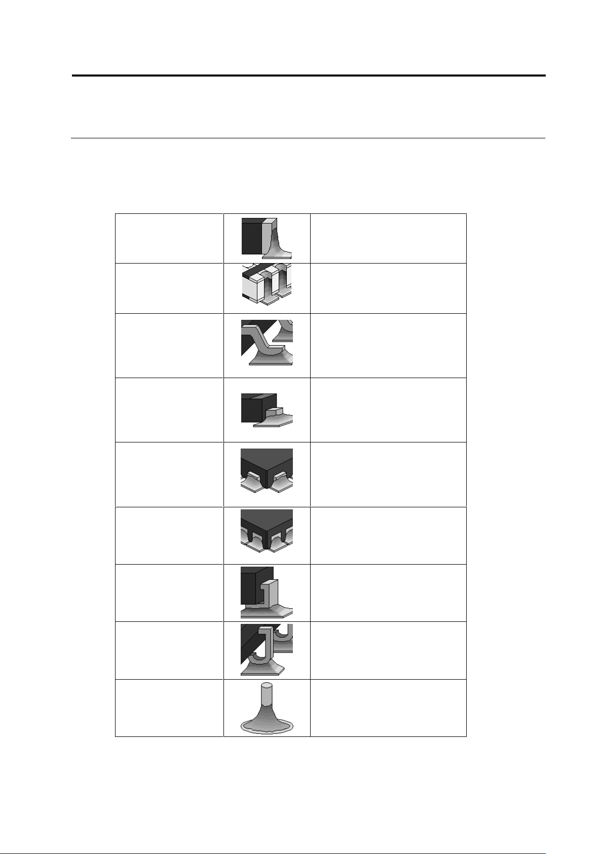
Electrode Types
This system provides inspection in a specific way depending on the defined electrode type.
The types of electrode that can be defined are determined according to the component types.
Electrode Type
Chip-Type Electrode
Chip Resistor
Chip Capacitor
Other Chip Components
MELF Component
Castellated Electrode
Resistor Array (Castellated
Electrode)
Gull-Wing Lead
2-Pin Mini-Mold Package
Transistor
Power Transistor
SOP, QFP
Connector
Other Lead Packages
Flat Lead
2-Pin Mini-Mold Package
Electrolytic Capacitor
Transistor
Power Transistor
Connector
Other Lead Packages
Micro-Lead
Resistor Array (Micro-Lead)
2-Pin Mini-Mold Package
Transistor
SON (Micro-Lead)
QFN (Micro-Lead)
Other Lead Packages
Non-Lead
Other Arrays (Non-Lead)
SON (Non-Lead)
QFN (Non-Lead)
Connector
Other Non-Lead Packages
Inward L-Lead
Inward L-Lead Package
J-Lead
SOJ
QFJ
Insertion Leads
Insertion Component
Chapter 2 Inspection Programming
2-10
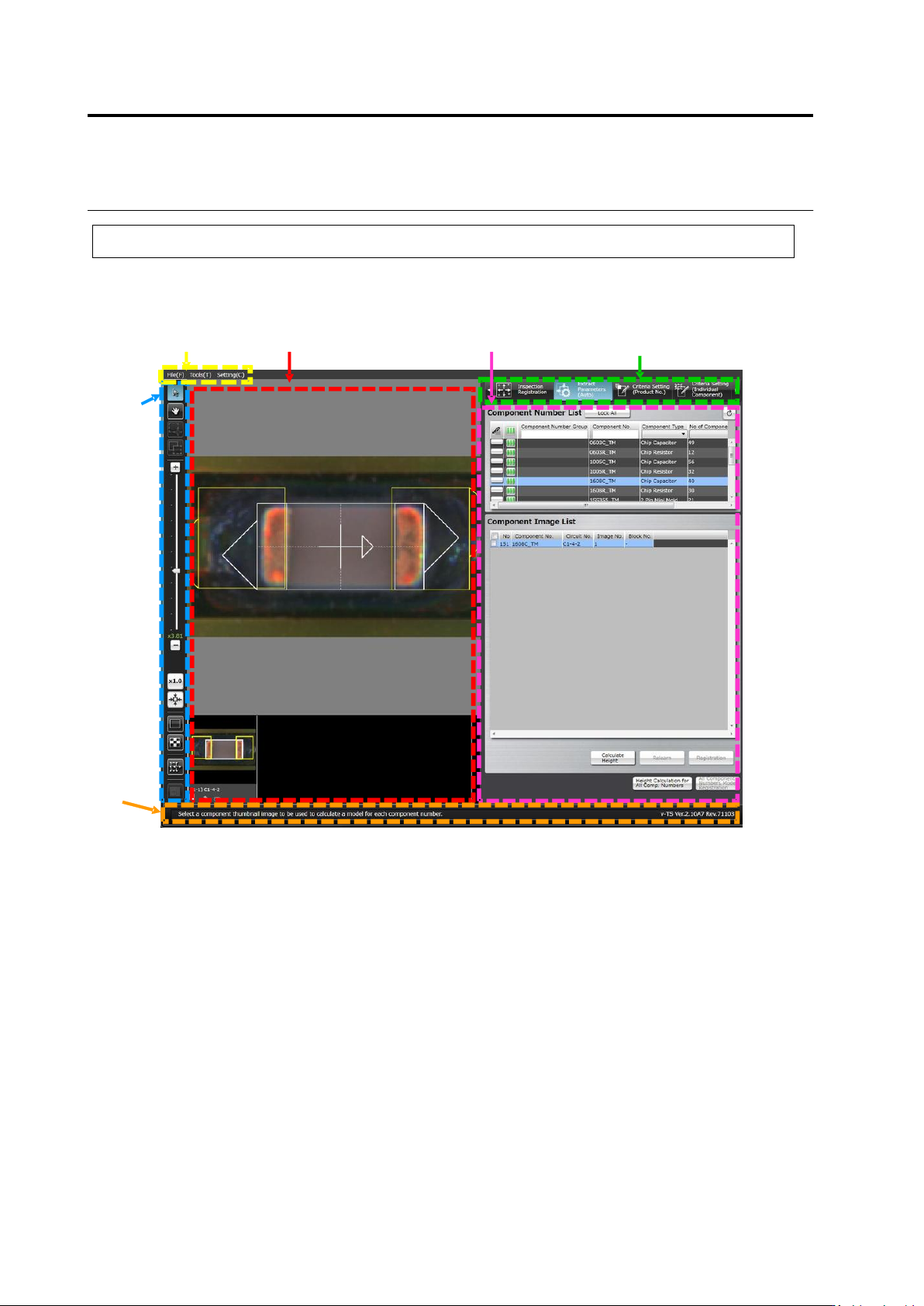
2.1.2 Configuration of the Editing Screen
The screenshot below shows the configuration of the Inspection Program Editing screen.
To view the editing screen, select a PCB you wish to edit from the inspection program list, and
click [Edit] in the bottom right corner of the screen.
(1) Menu Bar
Shows the following menu items:
・File Menu (Save, Save as Adjustment, Release, Recently Used Inspection Program, Reload,
Inspection Coverage, and Quit)
・Tool (PCB Image Management, Component Number Group Setting, Mass Production Image,
Move Component To Inspection Reference Position, Data Verification, Screen Brightness
Adjustment, Forced Lock Release, and Area Assistance)
・Setting (Set Inspection Program and Set Application)
(2) Status Display Area
Indicates the operation required on the currently displayed screen.
(1) Menu Bar
(3) Image Display Area
(6) Display Switch Tab
(5) Information Display Area
(4) Image
Operation
Buttons
(2) Status
Display Area
2.1 Basics of Teaching
2-11
(3) Image Display Area
Displays the relevant PCB image or component thumbnail images.
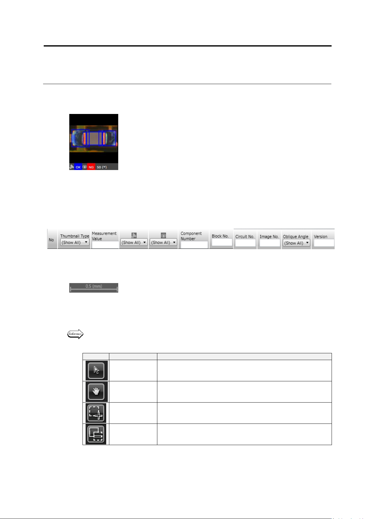
The description of component thumbnail image is shown below. The content displayed can be
viewed when model editing is performed on the PCB after a component number is created.
In the model list, the following thumbnail information is displayed:
However, it is not displayed unless clicking [Model Editing] in the bottom right corner of the
screen on the PCB after a component number is created.
A scale is displayed in the bottom right portion of the image display area. The length of the
scale on the image is displayed by number in mm according to the display magnification.
(4) Image Operation Buttons
Support the operation of the image display area e.g. selection of a window, image
magnification or reduction.
The functions of individual buttons are explained below.
Refer to "2.1.3 Image Display Area Operation" for the image operation details.
Mouse Tool Buttons
Button
Function
Operation
Select Window
Enables the selection and moving of a window using the mouse.
Click to select and drag and drop to move a window.
Move Field of
Vision
Enables the moving of the field of vision using the mouse on the
image display area.
Drag the image display area to move the field of vision.
Create Window
Enables the creation of a window using the mouse.
Drag and drop to create a window in accordance with the image.
Create Mask
Window
Enables the creation of a window using the mouse.
Drag and drop to create a window in accordance with the image.
(1) Presence of individual setup
(2) Image No.
(3) Image Type
(PCB Test Result/Model/Oblique Model//Mass Production Image/Mass
Production Image (not registered))
(4) Measured Value
(5) Judgment Result (OK/NG)
(6) Component Fault Name
(7) Visual Check Result (OK/NG/Acceptable/None)
(8) Component No. Name
(9) Component Block Unit No.
(10) Circuit No.
(11) Image No.
(12) Oblique View Angle
① ② ③ ④ ⑤ ⑥ ⑦ ⑧ ⑨ ⑩ ⑪