Omron V-TS Teaching Manual.pdf.pdf - 第140页
2.9 Setti ng Oblique Inspection 2- 113 2.9.3 S p e c if y in g O b l iq u e I n s pe c t i o n C o m p o n e n t an d D i r e c t i o n This section explains the procedure to s pecif y if oblique inspectio n is perform e…
Chapter 2 Inspection Programming
2-112
5.
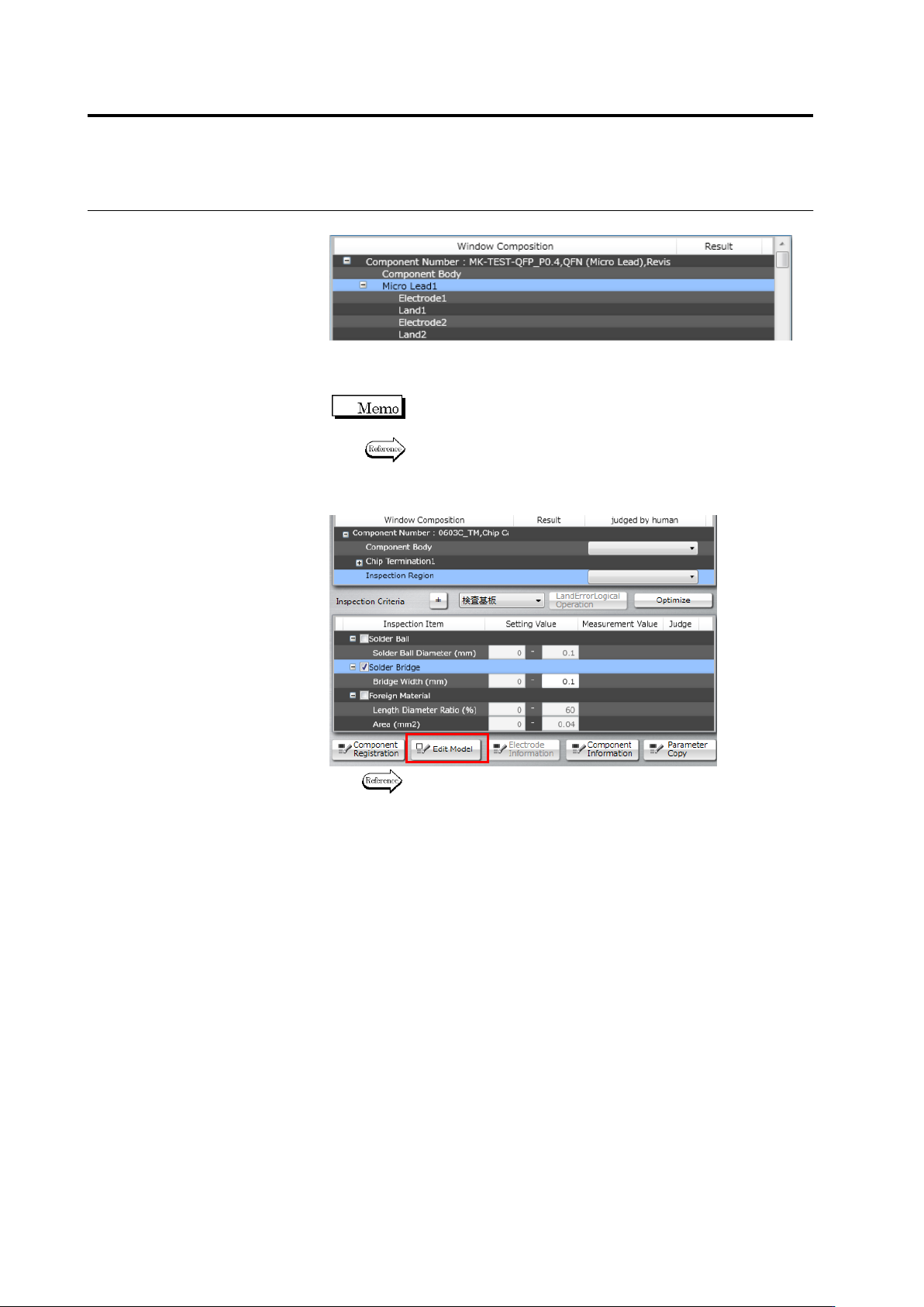
Select a window you wish to edit.
6.
Specify ON of OFF or the oblique inspection checkbox and edit
criteria values.
Component numbers cannot be edited if their oblique image is
not captured yet.
Refer to the Inspection Logic Manual for the details on the
inspection items.
7.
To edit characteristic parameters, click [Edit Model].
Refer to "2.15.3 Editing a Model" for the model editing
procedure.
2.9 Setting Oblique Inspection
2-113
2.9.3 Specifying Oblique Inspection Component and Direction
This section explains the procedure to specify if oblique inspection is performed or not, as well as
the procedure to set the direction of oblique inspection (if it is performed).
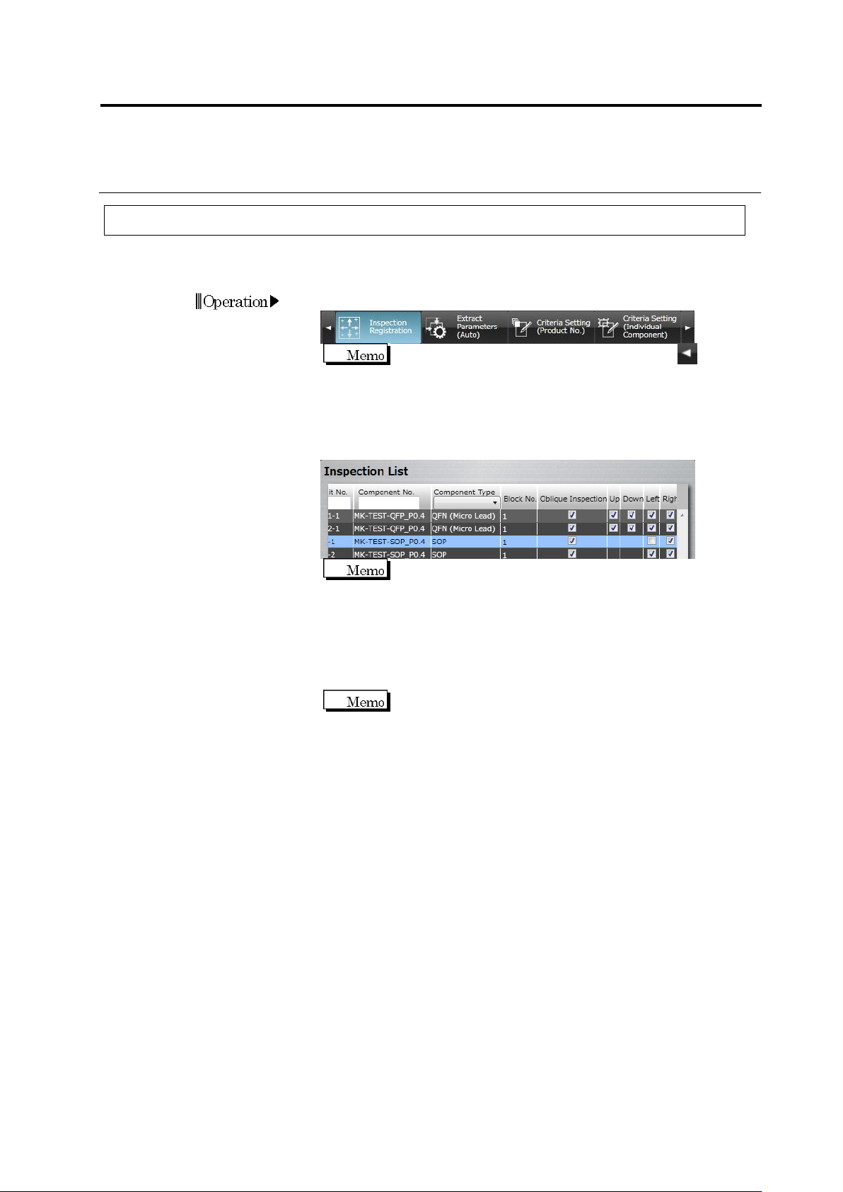
1.
Select the [Inspection Registration] tab.
If the [Inspection Registration] tab is hidden, click at the
left to display it.
2.
The display switches to the Inspection Registration screen.
Checkboxes are displayed at the Oblique Inspection column, and
the Top, Bottom, Left and Right columns in the direction of the
electrode window.
Slanted components (the component angle is other than 0°,
90°, 180°, or 270°) cannot be targets for oblique inspection
and therefore, checkboxes are not displayed for them.
Turn OFF the oblique inspection checkbox for components, if
oblique inspection is not performed for them. Turn OFF the
checkbox of specific directions, in which oblique inspection is not
performed, if there are any.
Turn OFF the direction where oblique inspection is obstructed
due to a large adjacent component.
Chapter 2 Inspection Programming
2-114
2.9.4 Including Oblique Inspection in PCB Test
Perform PCB testing on the PCB used to capture oblique image, to check the validity of the
oblique inspection criteria.
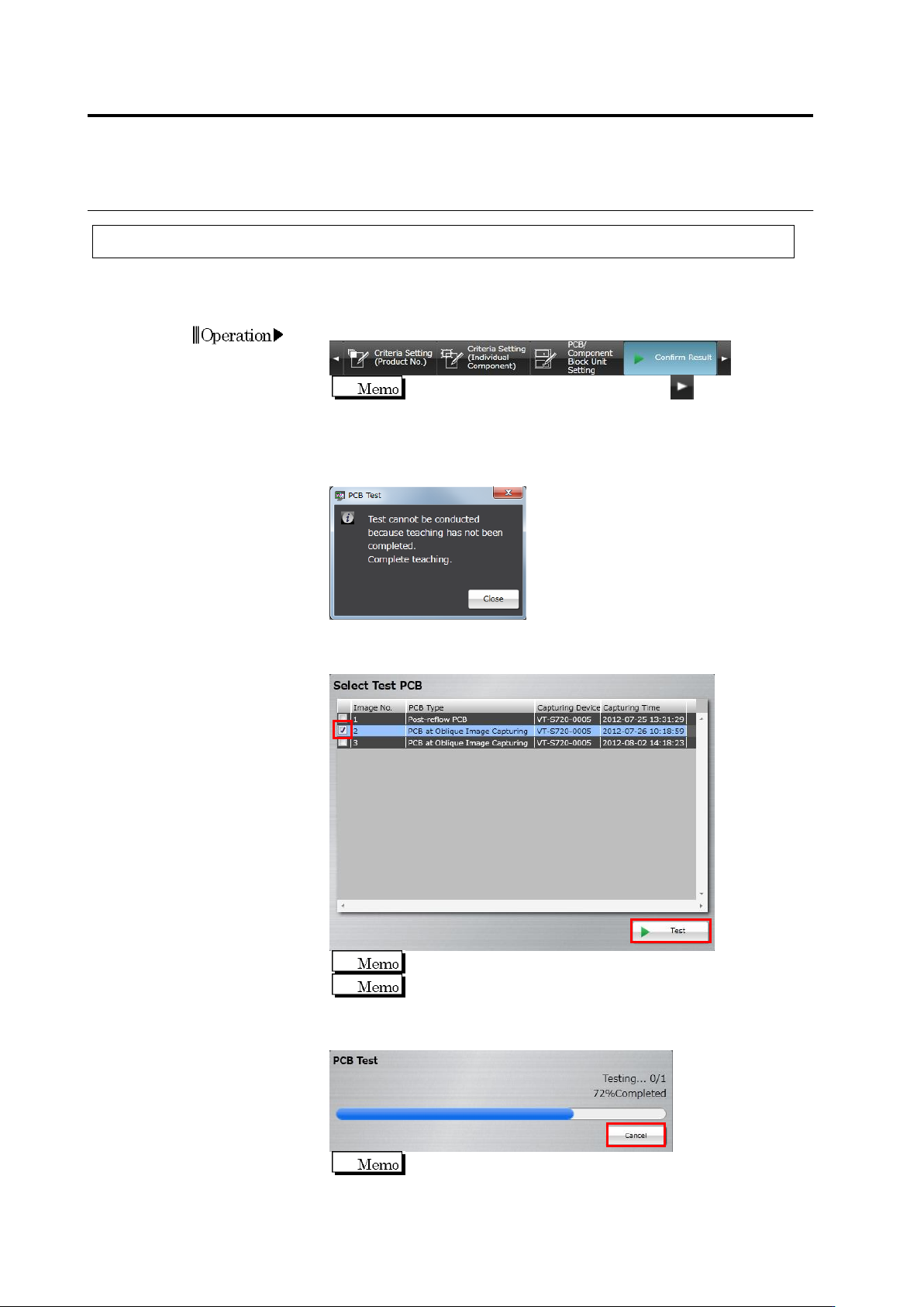
1.
Select the [Confirm Result] tab.
If the [Confirm Result] tab is hidden, click at the right to
display it.
The following dialog appears if direct view inspection teaching is not
complete for some component numbers. Click [Close], and complete
teaching for all component numbers.
2.
Turn ON the checkbox to which the PCB type is "PCB at Oblique
Image Capturing" or “Adjusted Image (Oblique)”, and click [Test].
Up to three PCBs can be selected.
The master PCB is displayed at the top.
The test starts and the progress is shown in the progress bar.
Click [Cancel] to abort testing.
The first test on a PCB used to capture oblique image requires
more time than following tests, due to the necessity of image
capture route calculation.