Omron V-TS Teaching Manual.pdf.pdf - 第86页
2.4 Registeri ng f or Insp ection 2- 59 2.4.5.2 Land Se tting Land windows are autom atically extracted and d isplayed on the sc reen, if they are not s pecified for the com ponent yet, based on the bare PCB im age. The …
Chapter 2 Inspection Programming
2-58
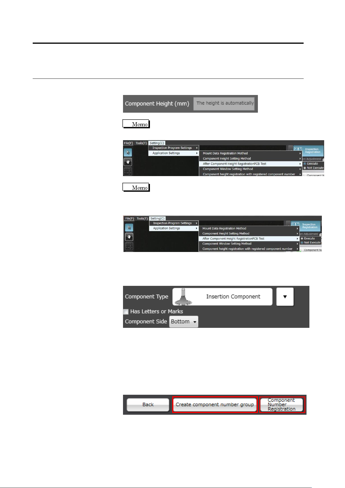
If you select auto calculation, you cannot enter a component height
manually.
To register the central value of the component height as the
result of the PCB test to the component number, select After
Component Height Registration PCB Test to [Execute].
If you select [Not Execute] for Component height registration
with registered component number, the height registration to
the already registered component number can be skipped. If
you do not need to change the height criteria, select [Not
Execute].
10.
If "Insertion Component" is selected, select the component surface
in the list box.
"Top" refers to the side where components bodies are seen, and
"Bottom", the side with inserted leads.
11.
Click [Next] to proceed to the Land Setting screen.
If you select "BGA/CSP" or "Others(Bottom Electrode)" for the
component type, [Component Number Registration] will appear
instead of [Next] as settings after land settings are not required.
Click [Component Number Registration] and set other unregistered
component numbers. To create a component number group based
on the configured component number, click [Create component
number group]. Component number registration is performed at the
same time.
2.4 Registering for Inspection
2-59
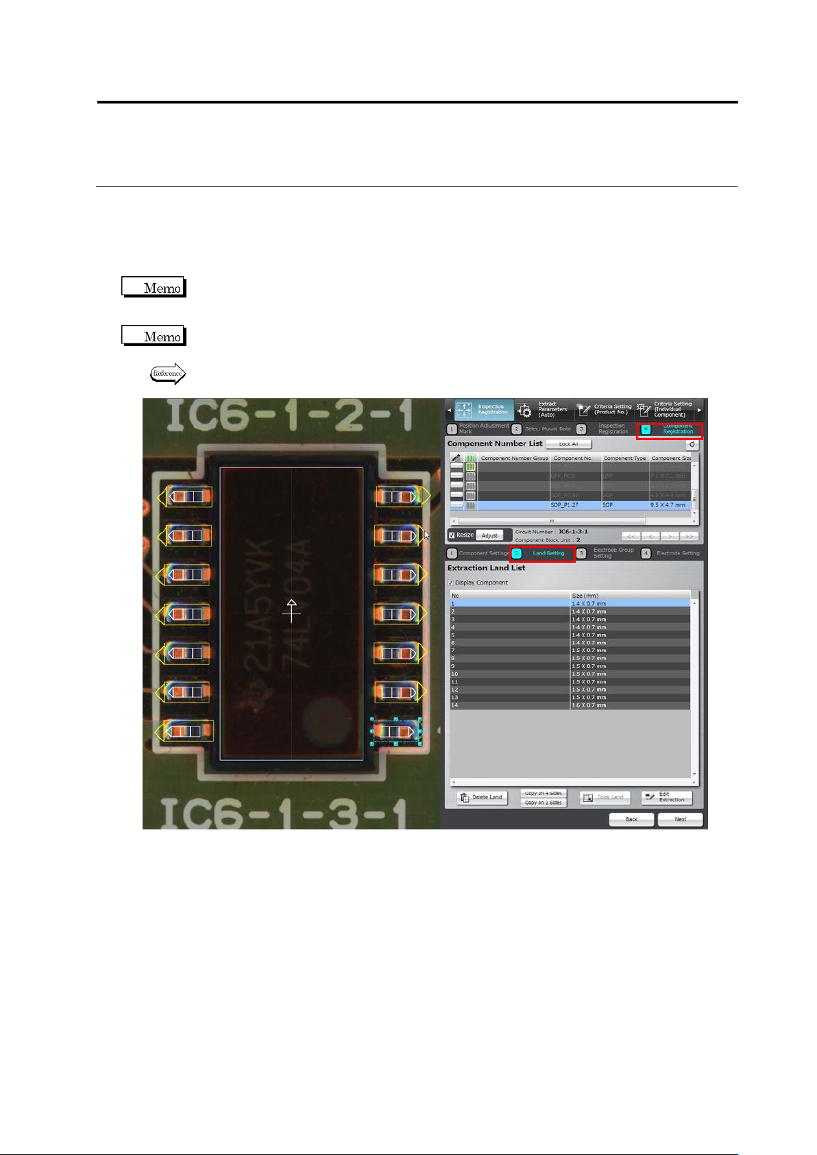
2.4.5.2 Land Setting
Land windows are automatically extracted and displayed on the screen, if they are not specified
for the component yet, based on the bare PCB image. The size and position of the auto-extracted
land windows can be adjusted on the screen.
You cannot select the target component on the land settings screen. To change the component,
click [Back] to return to the component settings screen and select a component, adjust the
Component Body Window, and then click [Next].
Land windows must be manually added or deleted, if the auto extraction failed (due to the wrong
number of land windows).
Refer to “Add a land window” or “Delete a land window” of “2.4.5.2 Land Setting” for the
procedures to add or delete land windows.
Chapter 2 Inspection Programming
2-60
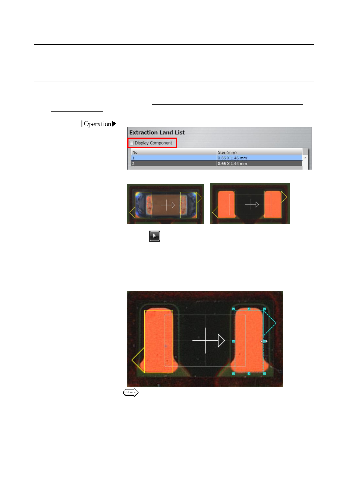
・ Adjust the Land Size
Adjust the size of auto-extracted land windows in accordance with the bare PCB image.
This operation is not usually required. Perform it only when the PCB is a leveler board or a raw
PCB is unavailable.
1.
Deselect the [Display Component] checkbox.
The image on the display area switches to the bare PCB image.
<"Display Component" ON> <"Display Component" OFF>
2.
Select (Select Window) in the Image Operation tool bar, if it is
not selected.
3.
Select the land for adjusting the size.
Click the land window in the image display area, or click the land in
the Extraction Land List.
4.
Adjust the size of the selected land window.
Refer to "2.1.3 Image Display Area Operation" for the image display
area operation.
Operation