Omron V-TS Teaching Manual.pdf.pdf - 第155页
Chapter 2 Insp ection Progr amming 2- 128 Item Name Description Setting Item ON/OFF Criteria Value Output FilletLength Fillet Length FilletJointLength Fillet Joint Width - EndJointWidth End Joint Width FilletHe…
2.13 Outputting Inspection Coverage
2-127
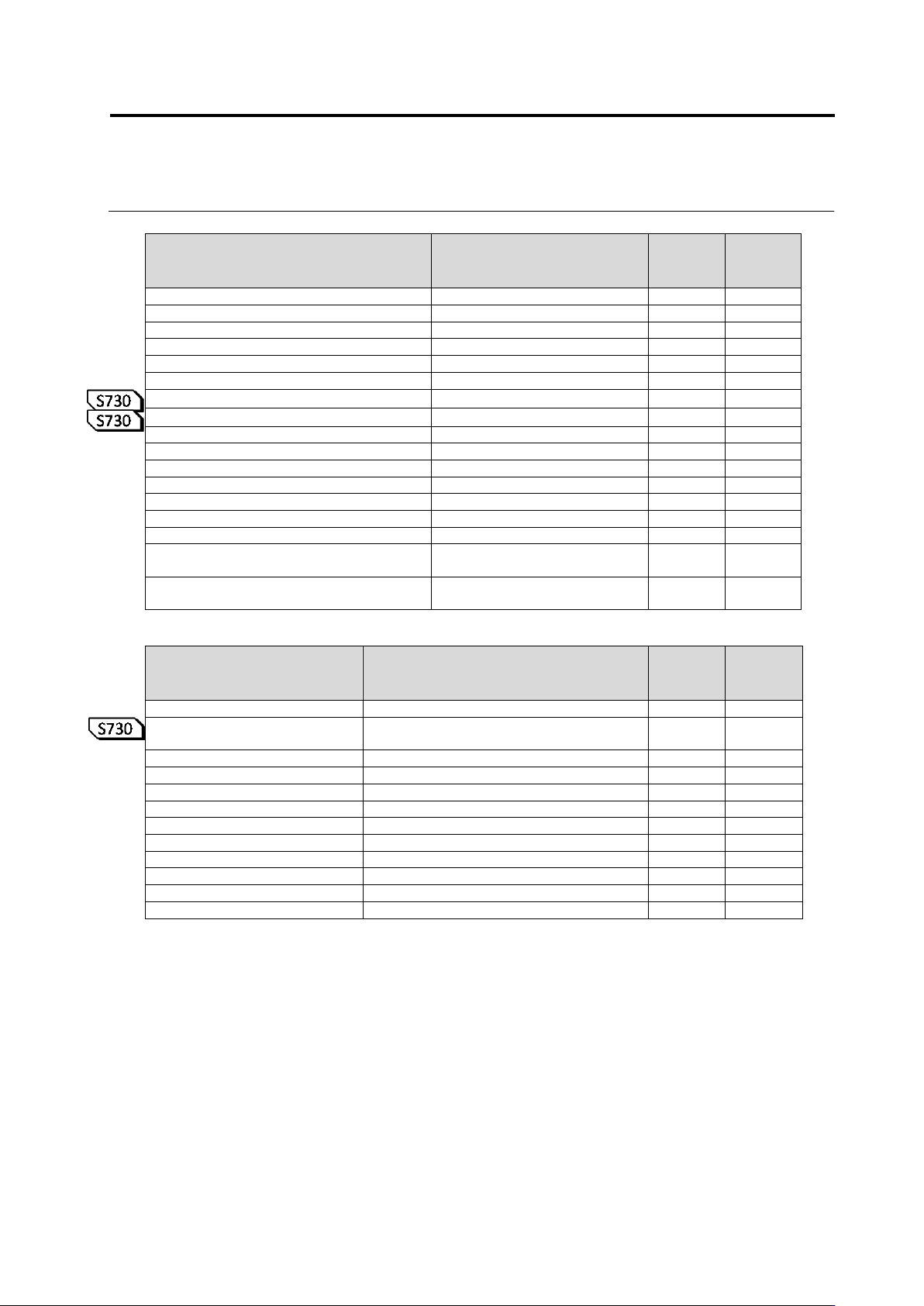
Electrode Window
Item Name
Description
Setting
Item
ON/OFF
Criteria
Value
Output
ElectrodeInspection
Electrode Inspection
-
ElectrodeOffset
Electrode Offset
-
SideOverhang
Side Overhang
EndOverhang
End Overhang
EndOverlap
End Overlap
LiftedElectrode
Lifted Electrode
-
VerticallyLiftedElectrode
Lifted Electrode
ElectrodeCoplanarity
Electrode Coplanarity
ElectrodeLength
Electrode Length
ElectrodeArea
Electrode Area
Exposed Electrode Toe
Exposed Electrode Toe
ElectrodeColorDispersion
Electrode Color Dispersion
ElectrodeSideBend
Electrode Side Bend
LiftedElectrodeOblique
Electrode Posture (Oblique)
-
ElectrodeHeightOblique
Electrode Height (Oblique)
ExposedElectrodeToeOblique
Exposed Electrode Toe
(Oblique)
ElectrodeColorDispersionOblique
Electrode Color Dispersion
(Oblique)
Land Window
Item Name
Description
Setting
Item
ON/OFF
Criteria
Value
Output
FilletInspection
Fillet Inspection
-
LogicMethodType
Associated with component/electrode
height
-
WettingAngle
Joint Wetting Angle
-
LandWetting
Land Wetting
-
Center
Center
BothEnds
Both Ends
ComponentWetting
Component Wetting
-
CenterOfToe
Center of Toe
BothEndsOfToe
Both Ends of Toe
CenterOfSide
Center of Side
BothEndsOfSide
Both Ends of Side
FilletHeight
Fillet Height
Chapter 2 Inspection Programming
2-128
Item Name
Description
Setting
Item
ON/OFF
Criteria
Value
Output
FilletLength
Fillet Length
FilletJointLength
Fillet Joint Width
-
EndJointWidth
End Joint Width
FilletHeight
Fillet Height
-
SideJointLength
Side Joint Length
FilletHeight
Fillet Height
-
ExposedBasisMetal
Exposed Basis Metal
LandError
Land Error
-
Region1-5
Setting 1 to 5
FollowElectrode
Follow Electrode
-
DistanceDesignation
Specify Distance
LogicalOperationWithWettabilit
yInspection
Relieve Wettability Inspection
-
ForeignMaterialOnLand
Foreign Material (On Land)
ExposedBasisMetalOblique
Exposed Basis Metal (Oblique)
LandErrorOblique
Land Error (Oblique)
Inspection Region Window
Item Name
Description
Setting
Item
ON/OFF
Criteria
Value
Output
SolderBall
Solder Ball
-
SolderBallDiameter
Solder Ball Diameter
-
Rate
Rate
-
AreaRate
Rate of area
-
RegionLimit
Limitation of inspection region
SolderBridge
Solder Bridge
-
BridgeWidth
Bridge Width
-
ForeignMaterial
Foreign Material
-
LengthDiameterRatio
Length Diameter Ratio
-
Area
Area
-
SolderBallOblique
Solder Ball (Oblique)
-
SolderBallDiameter
Solder Ball Diameter
-
SolderBridgeOblique
Solder Bridge (Oblique)
-
BridgeWidth
Bridge Width
-
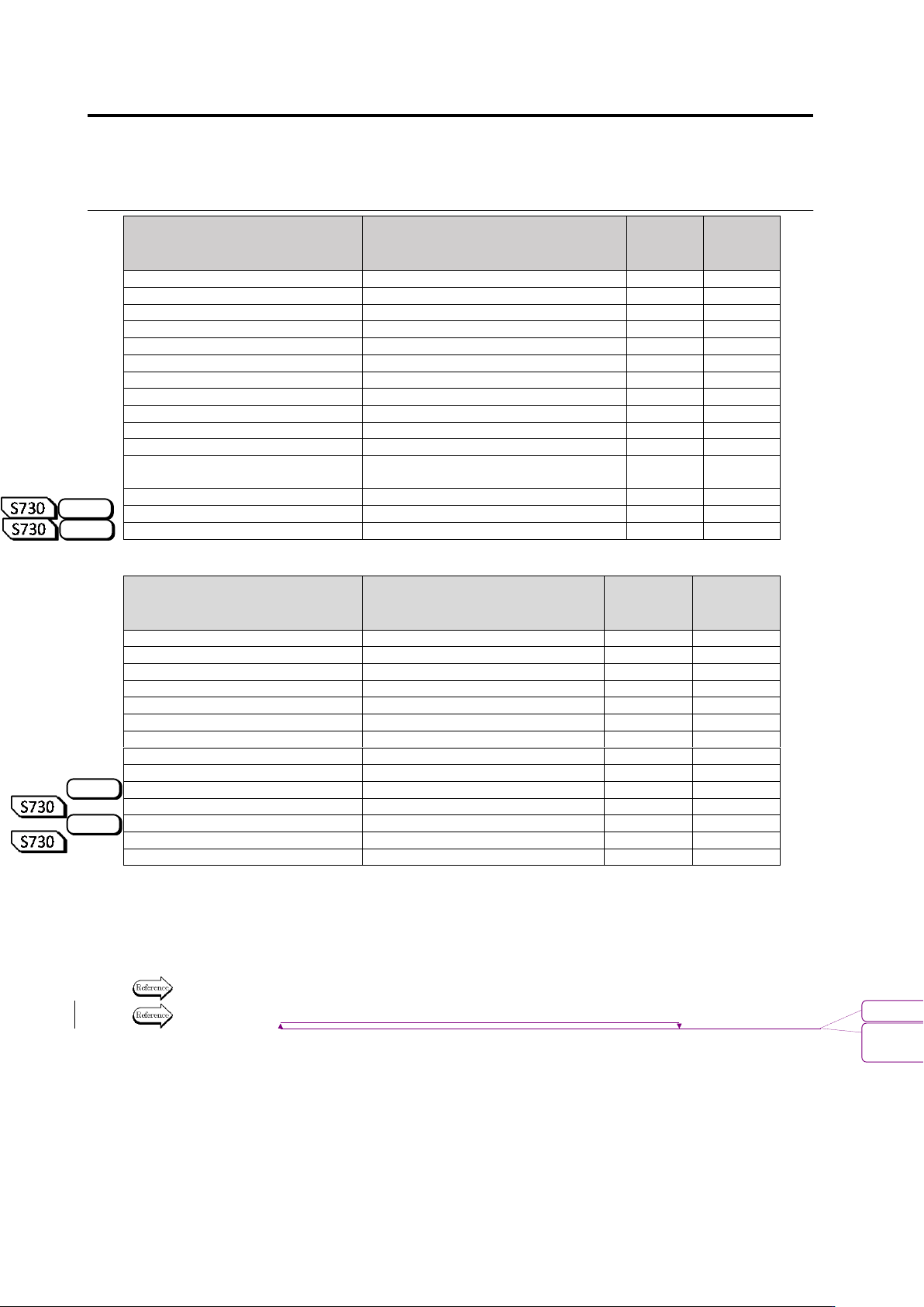
The logical expressions for the inspection result judgment is output to the DetailSetting item at
the tail end.
The detail of the expressions specified for each electrode group are output in the order shown in
the detailed setting screen.
Refer to the land window output items shown in the previous page for the output items description.
Refer to "2.15.4 Optimizing Boolean Expressions and Inspection Criterion Values" for logical
expressions for the inspection result judgement.
The following is an example of inspection coverage output.
S720A
S720A
S720A
S720A
書式変更: フォント : 9 pt
削除
: Optimizing Boolean Expressions and
Inspection Criterion Values

2.13 Outputting Inspection Coverage
2-129
No
CircuitID
Componen
Revision
ComponrntTy
Compo
Window
Individual
Component
FollowCom
AngleMeasu
LowerLimit
UpperLimit
1005R
5
ChipResister
Component
True
True
0
7
1005R
5
ChipResister
ChipTermination1
1005R
5
ChipResister
InspectionRange
0
7
62
C1-3-1
1005R
5
ChipResister
1
Component
False
True
True
62
C1-3-1
1005R
5
ChipResister
1
ChipTermination1
False
62
C1-3-1
1005R
5
ChipResister
1
Electrode1
False
62
C1-3-1
1005R
5
ChipResister
1
Land1
False
62
C1-3-1
1005R
5
ChipResister
1
Electrode2
False
62
C1-3-1
1005R
5
ChipResister
1
Land2
False
62
C1-3-1
1005R
5
ChipResister
1
InspectionRange
False