Omron V-TS Teaching Manual.pdf.pdf - 第80页
2.4 Registeri ng f or Insp ection 2- 53 2.4.5 Component Registration Position the Com ponent Body W indow, land windows and electrode windows on a s ample component of individual com ponent numbers and set the component …
Chapter 2 Inspection Programming
2-52
Click the added component number to edit its
description (name).
4. Click [OK] to close the dialog. Display the component to add
in the image display area and click the center of it.
Change the Circuit Number Description
Select the component in the inspection list, and click the circuit
number.
The textbox becomes editable. Enter the new name.
A circuit number can be described within 16 single-byte characters.
Lowercase alphabet characters are changed to
uppercase when entering.
Allowed symbols ! # $ % & ' ( ) - = ^ ~ @` [ { ;+ } ] ,._␣
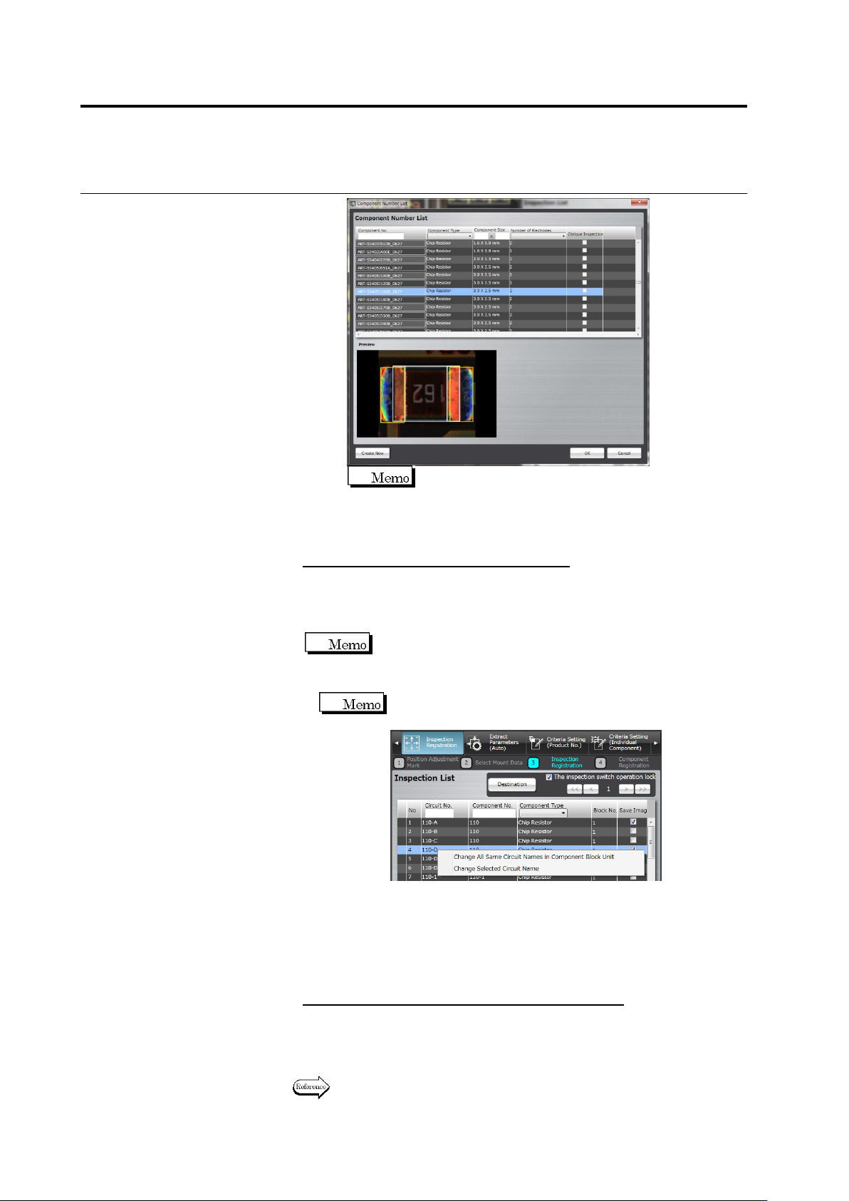
To change a circuit name with a customer-specific inspection
program, you can select a target as shown below
.
①
Changing all circuit names that are the same in a
component block unit
You can change all circuit number names that are the same
in one component block unit.
②
Changing a selected circuit name
You can change a circuit name being selected.
To save the images of the specified component
On the inspection list, set ON the checkbox on the [Save image]
column of the component saved.
3.
Click [Next] to proceed to the Component Registration screen.
Refer to the next section for the component registration procedure.
2.4 Registering for Inspection
2-53
2.4.5 Component Registration
Position the Component Body Window, land windows and electrode windows on a sample
component of individual component numbers and set the component and electrode information
for them.
2.4.5.1 Component Setting
Set the component information for each component number.
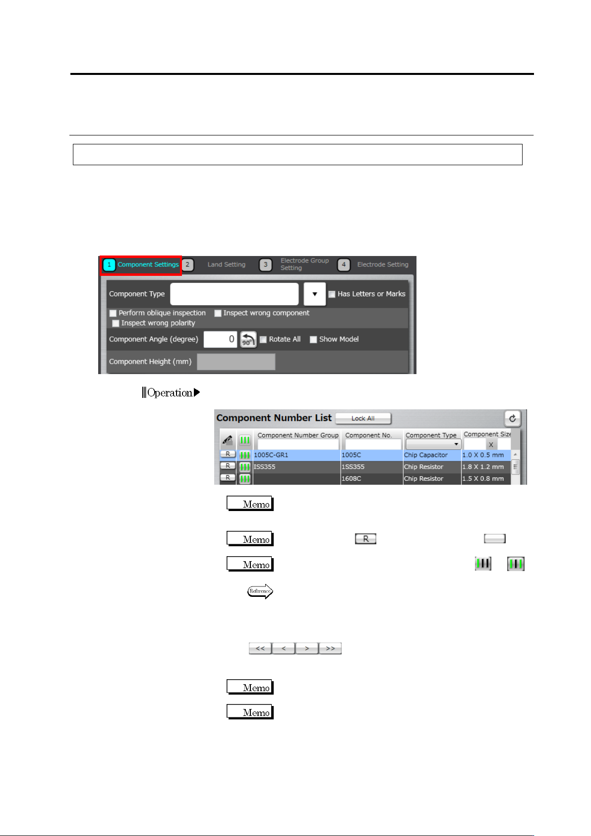
1.
Select the component number for the setting in the Component
Number List.
If the component number is registered in the library and the
component information obtained from the library is used, this
setting is not necessary.
When the status is (locked), click it to unlock (not
locked) the component number.
If the teaching status of the component number is or ,
perform automatic window adjustment.
Refer to (5) Information Display Area on “2.1.2 Configuration of
the Editing Screen” for details on the status display of the
component number and auto adjustment procedure.
If there are multiple components with the same component number,
click below the Component Number List to
switch the component displayed in the image display area. Select
the sample component.
Click [<<] to display the top component and [>>], the last
component.
Select a component image rendered in clear colors, without
noise such as shadow, as the sample component, which can
enhance the accuracy of auto component window positioning
for the same component number.
Operation
Chapter 2 Inspection Programming
2-54
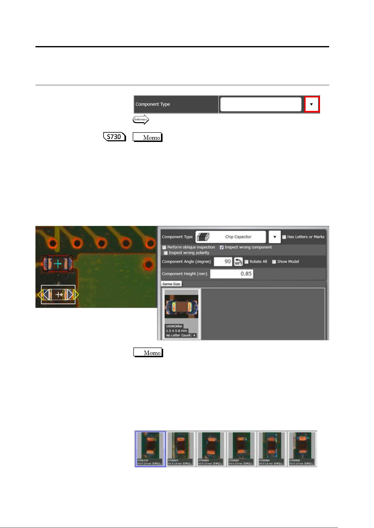
2.
Select the component type in the list box.
Refer to "2.1.1 Basic Knowledge of Teaching", "Component Types"
for the types of components.
When a chip resistor, chip capacitor, or other chip/ melf/
component type is selected, the component body window is set up
automatically. If you do not wish this window to be set up
automatically, select [Setting] - [Application Settings] - [Component
Window Setting Method] -> [Manual Settings] on the menu bar.
3.
Find groups with the same shape and same color in the component
number group list.
When setting the “Same size” toggle button ON, if you found an
appropriate component number group, click the thumbnail and
select [Add], then go to step 9.
If you couldn't, go to step 4.
Component number groups are configured based on the
following guideline.
- Components with the same shape/size/electrode count shall
belong to the same group.
- A group shall be configured for each color, e.g. white, black, and
brown based on the visual check.
- A group shall be configured for each component color if there are
multiple component colors.
(e.g.) Configuring a group of chip resistor (black) with the same
shape and size.