Omron V-TS Teaching Manual.pdf.pdf - 第38页
2.1 Bas ics of Teaching 2- 11 (3) Im age Display Area Displays the relevant PC B i mage or com ponent thumbnail images. The description of com ponent t humbnail im age is s hown below . T he con tent displa yed can be vi…
Chapter 2 Inspection Programming
2-10
2.1.2 Configuration of the Editing Screen
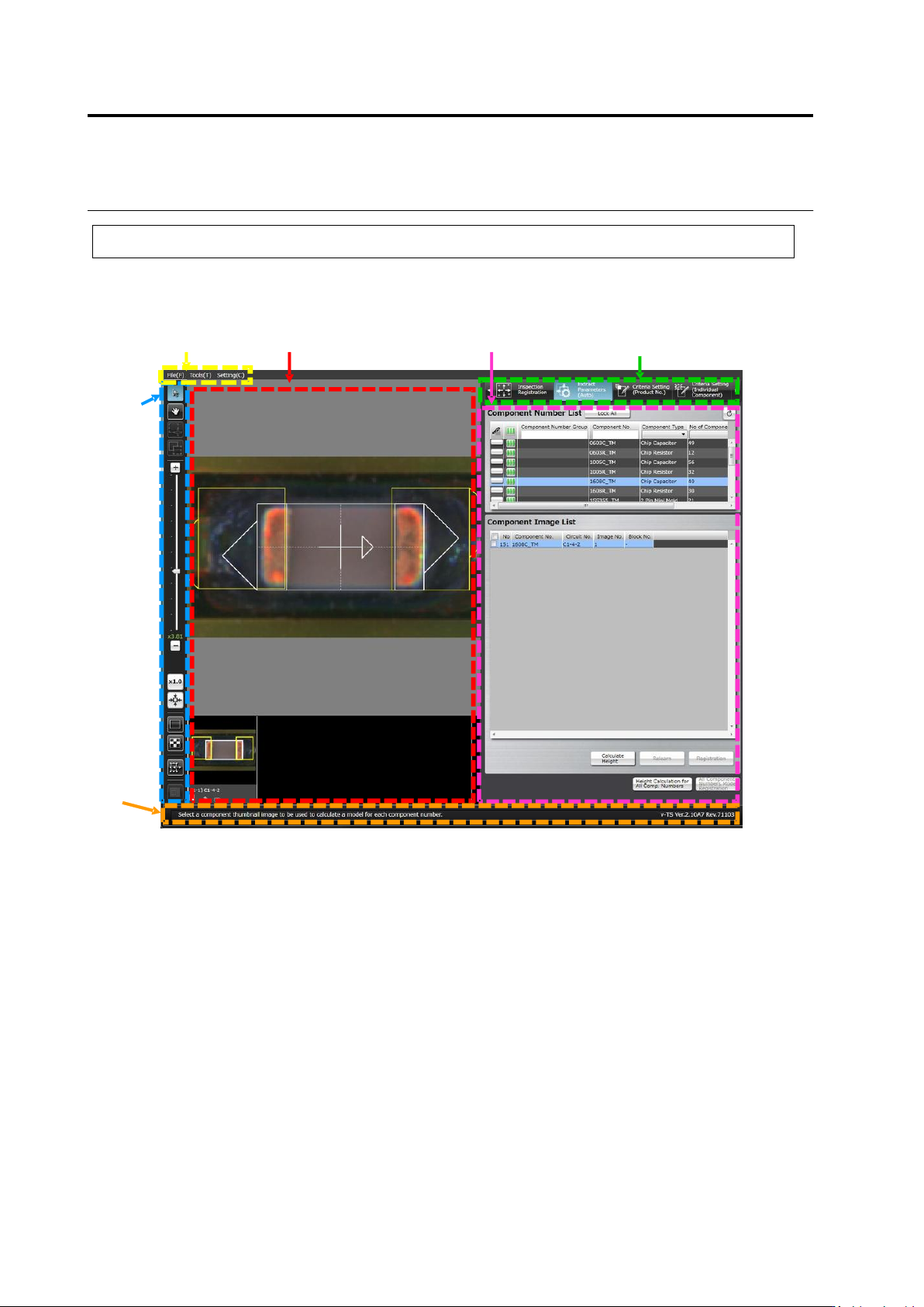
The screenshot below shows the configuration of the Inspection Program Editing screen.
To view the editing screen, select a PCB you wish to edit from the inspection program list, and
click [Edit] in the bottom right corner of the screen.
(1) Menu Bar
Shows the following menu items:
・File Menu (Save, Save as Adjustment, Release, Recently Used Inspection Program, Reload,
Inspection Coverage, and Quit)
・Tool (PCB Image Management, Component Number Group Setting, Mass Production Image,
Move Component To Inspection Reference Position, Data Verification, Screen Brightness
Adjustment, Forced Lock Release, and Area Assistance)
・Setting (Set Inspection Program and Set Application)
(2) Status Display Area
Indicates the operation required on the currently displayed screen.
(1) Menu Bar
(3) Image Display Area
(6) Display Switch Tab
(5) Information Display Area
(4) Image
Operation
Buttons
(2) Status
Display Area
2.1 Basics of Teaching
2-11
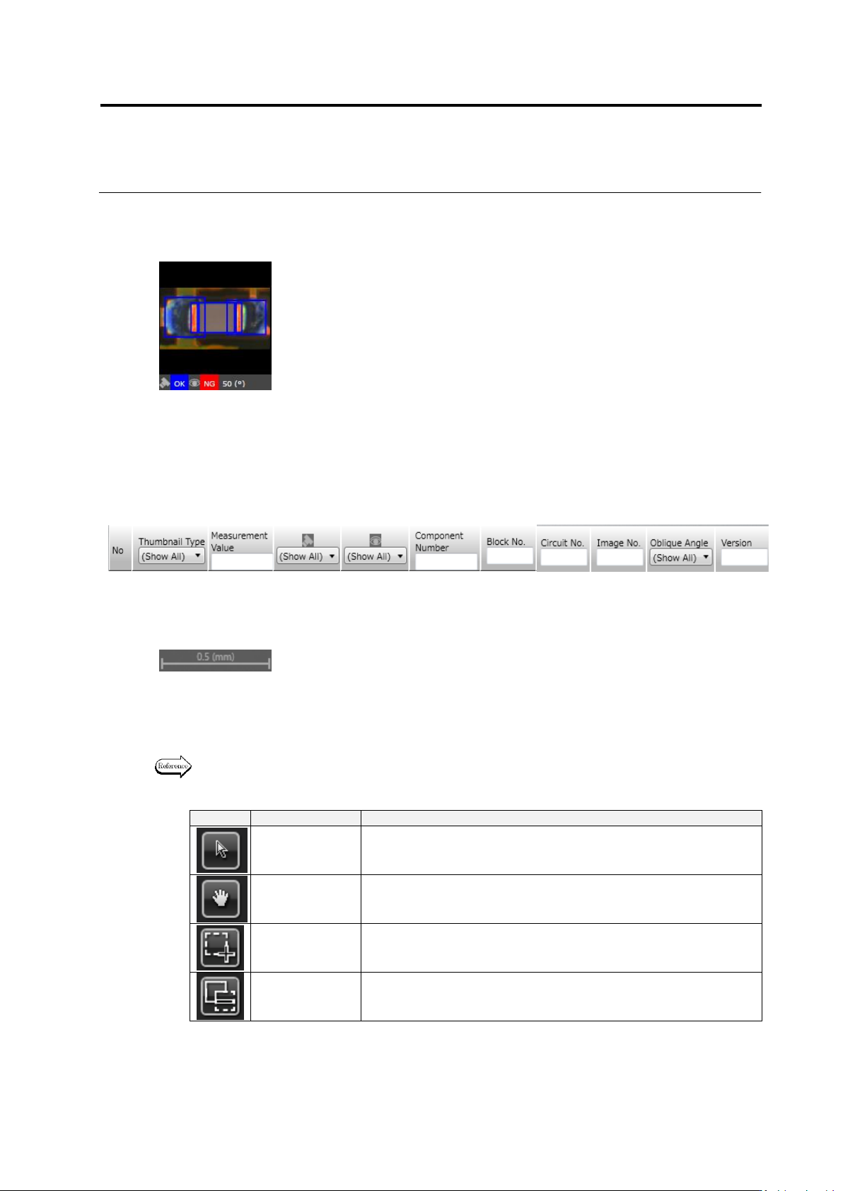
(3) Image Display Area
Displays the relevant PCB image or component thumbnail images.
The description of component thumbnail image is shown below. The content displayed can be
viewed when model editing is performed on the PCB after a component number is created.
In the model list, the following thumbnail information is displayed:
However, it is not displayed unless clicking [Model Editing] in the bottom right corner of the
screen on the PCB after a component number is created.
A scale is displayed in the bottom right portion of the image display area. The length of the
scale on the image is displayed by number in mm according to the display magnification.
(4) Image Operation Buttons
Support the operation of the image display area e.g. selection of a window, image
magnification or reduction.
The functions of individual buttons are explained below.
Refer to "2.1.3 Image Display Area Operation" for the image operation details.
Mouse Tool Buttons
Button
Function
Operation
Select Window
Enables the selection and moving of a window using the mouse.
Click to select and drag and drop to move a window.
Move Field of
Vision
Enables the moving of the field of vision using the mouse on the
image display area.
Drag the image display area to move the field of vision.
Create Window
Enables the creation of a window using the mouse.
Drag and drop to create a window in accordance with the image.
Create Mask
Window
Enables the creation of a window using the mouse.
Drag and drop to create a window in accordance with the image.
(1) Presence of individual setup
(2) Image No.
(3) Image Type
(PCB Test Result/Model/Oblique Model//Mass Production Image/Mass
Production Image (not registered))
(4) Measured Value
(5) Judgment Result (OK/NG)
(6) Component Fault Name
(7) Visual Check Result (OK/NG/Acceptable/None)
(8) Component No. Name
(9) Component Block Unit No.
(10) Circuit No.
(11) Image No.
(12) Oblique View Angle
① ② ③ ④ ⑤ ⑥ ⑦ ⑧ ⑨ ⑩ ⑪
Chapter 2 Inspection Programming
2-12
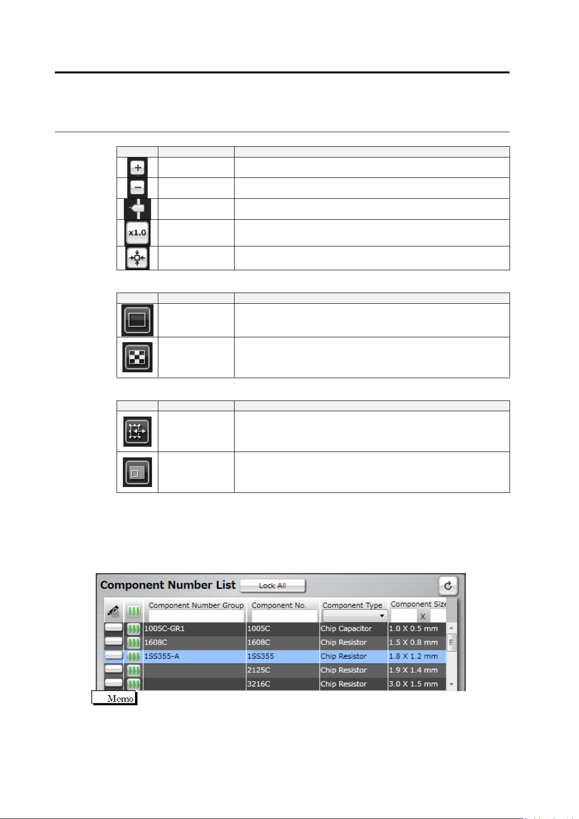
Display Magnification Buttons
Button
Function
Operation
Magnify
Magnifies the image display area by one step increment.
(Max. ratio: 10.0 times)
Reduce
Reduces the image display area by one step increment.
(Min. ratio: 0.01 times)
Magnify/Reduce
The slider to magnify or reduce the image display area.
Slide up the slider to magnify, and down to reduce.
Original Size
Displays the image in the display area at the same magnification of
pixels.
Entire View
Displays the entire image of the PCB in the display area.
Display Switch Buttons (Only effective on screens where thumbnails can be displayed)
Button
Function
Operation
PCB Display
Only displays the PCB image in the image display area.
Clicking this button again brings back the default display (PCB
image and component thumbnail images).
Component
Thumbnail
Display
Clicking the button displays the component thumbnails in the image
display area.
Clicking this button again brings back the default display (PCB
image and component thumbnail images).
Auxiliary Tool Buttons
Button
Function
Operation
Window
Adjustment
Dialog
Displays the window adjustment dialog.
The dialog provides the adjustment of window position and size with
buttons.
Used when fine adjustment with the mouse is difficult.
PCB Map
Displays the PCB map.
Shows the current field of vision of the image display area on the
PCB map in the form of a window. The field of vision can be moved
by drag and drop of the window.
(5) Information Display Area
Editing operation can be proceeded while checking the information of individual components
such as the component number list and inspection criteria.
■ Component Number List
The following shows the operation procedures of the Component Number List.
The Component Number List comprises the Component Setting, Component Registration
(Auto) and Criteria Setting (Product No.) screens.