Omron V-TS Teaching Manual.pdf.pdf - 第78页
2.4 Registeri ng f or Insp ection 2- 51 1. Check that the com ponents to inspect a nd their m ount positions are available and read y for registration by mov ing the field of vision on the image displa y area or selectin…
Chapter 2 Inspection Programming
2-50
2.4.4 Inspection Registration
Register components to inspect based on the component information in the loaded mount data.
Also the components whose images are saved while inspection is performed can be selected.
Specify the inspection direction for the component numbers for oblique inspection, individually for
each component.
Refer to "2.9.3 Specifying Oblique Inspection Component and Direction" for the procedure to specify the
oblique inspection direction.
The software normally detects misalignment of the component position
automatically, and adjust it automatically from the position of the mount data.
When registering the component position in the position of the mound data to inspect misalignment
based on the mount data, turn OFF automatic adjustment by the following steps.
(The ON/OFF setting of automatic adjustment is saved in the v-TS terminal. This setting is
used by any inspection program.)
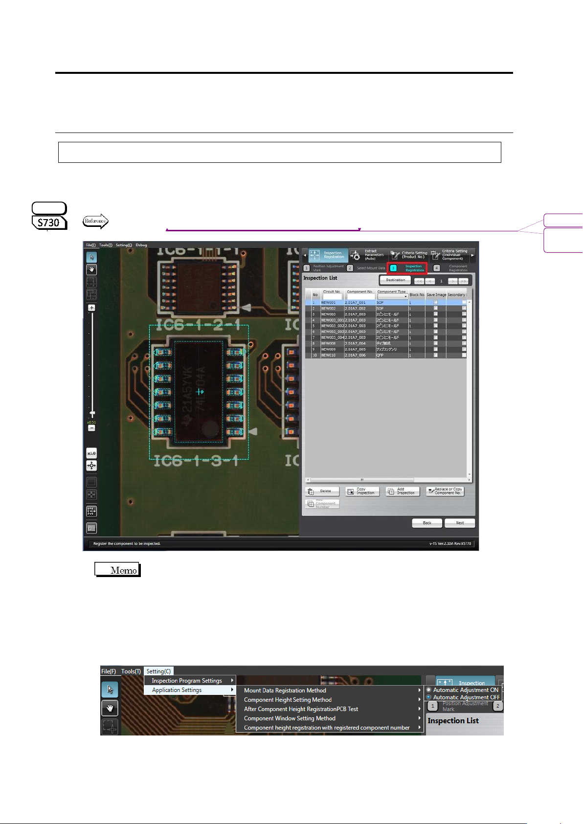
1. Select [Setting] - [Application Settings] - [Mount Data Registration Method], and check
[Automatic Adjustment OFF].
2. Execute inspection registration using the operation procedure below.
S720A
書式変更: フォント : (英) Arial, 9 pt
削除: Specifying Oblique Inspection
Component and Direction
2.4 Registering for Inspection
2-51
1.
Check that the components to inspect and their mount positions are
available and ready for registration by moving the field of vision on
the image display area or selecting the components in the
Inspection List.
Refer to "2.1.2 Configuration of the Editing Screen" for the image
display area operation.
2.
Delete, add or rename the components for inspection as required.
Delete Components from the Inspection List
Select the component to delete in the Inspection List and click
[Delete].The "+" mark of the deleted component is not displayed in
the image display area any more.
A component can also be selected by switching the image
display area to the Select Window mode and clicking the "+"
mark with the mouse directly.
Refer to "2.1.2 Configuration of the Editing Screen" for the
image display area operation.
Add Components to the Inspection List
Copy an Existing Component
1. Select the component to copy in the Inspection List and click
[Copy Inspection].
2. Click the center of the copy destination component in the
image display area.
3. After completing copying, click [Copy Inspection] to exit.
The inspection windows are copied in the same sizes as the
original. However, the inspection criteria common to the
component number is specified, if the original component is
individually set to specific criteria.
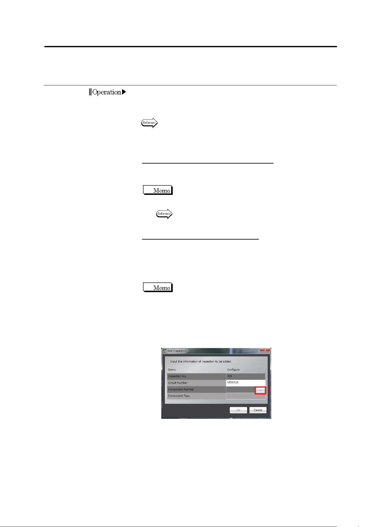
Specify the Component Number
1. Click [Add Inspection].
2. Enter the circuit number and click […] to select the
component number.
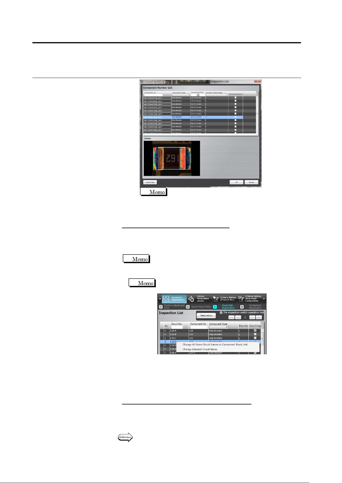
3. The Component Number List is displayed.
To add a new component number, click [Create New].
The new component number is added at the last row of the
Component Number List.
Select the component number to add for inspection and click
[OK].
Chapter 2 Inspection Programming
2-52
Click the added component number to edit its
description (name).
4. Click [OK] to close the dialog. Display the component to add
in the image display area and click the center of it.
Change the Circuit Number Description
Select the component in the inspection list, and click the circuit
number.
The textbox becomes editable. Enter the new name.
A circuit number can be described within 16 single-byte characters.
Lowercase alphabet characters are changed to
uppercase when entering.
Allowed symbols ! # $ % & ' ( ) - = ^ ~ @` [ { ;+ } ] ,._␣
To change a circuit name with a customer-specific inspection
program, you can select a target as shown below
.
①
Changing all circuit names that are the same in a
component block unit
You can change all circuit number names that are the same
in one component block unit.
②
Changing a selected circuit name
You can change a circuit name being selected.
To save the images of the specified component
On the inspection list, set ON the checkbox on the [Save image]
column of the component saved.
3.
Click [Next] to proceed to the Component Registration screen.
Refer to the next section for the component registration procedure.