Omron V-TS Teaching Manual.pdf.pdf - 第294页
Appendix 7. Positio n Correction/Extractio n a- 17 4) If not consistent, change the position or s ize of the land window .
Appendix 7. Position Correction/Extraction
a-16
2. Inspection screen position correction
In the inspection screen, recognize the land, and correct the position of the entire captured inspection
screen.
Inspection result
Component image (PCB test)
Cause
Confirmation and repair method
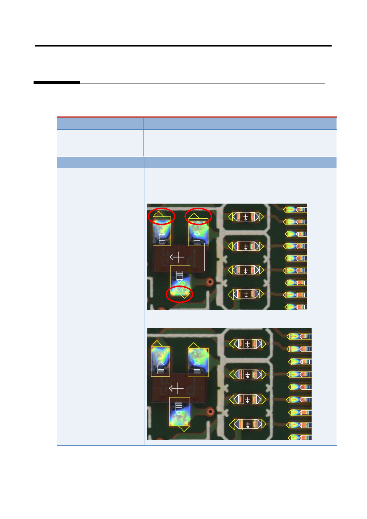
The position of the land
window is not appropriate.
1) Move to the “Criteria Setting” tab.
2) Confirm that the position and size of the land window are
consistent with those of the image.
3) If not consistent, change the position or size of the land window.
Appendix 7. Position Correction/Extraction
a-17
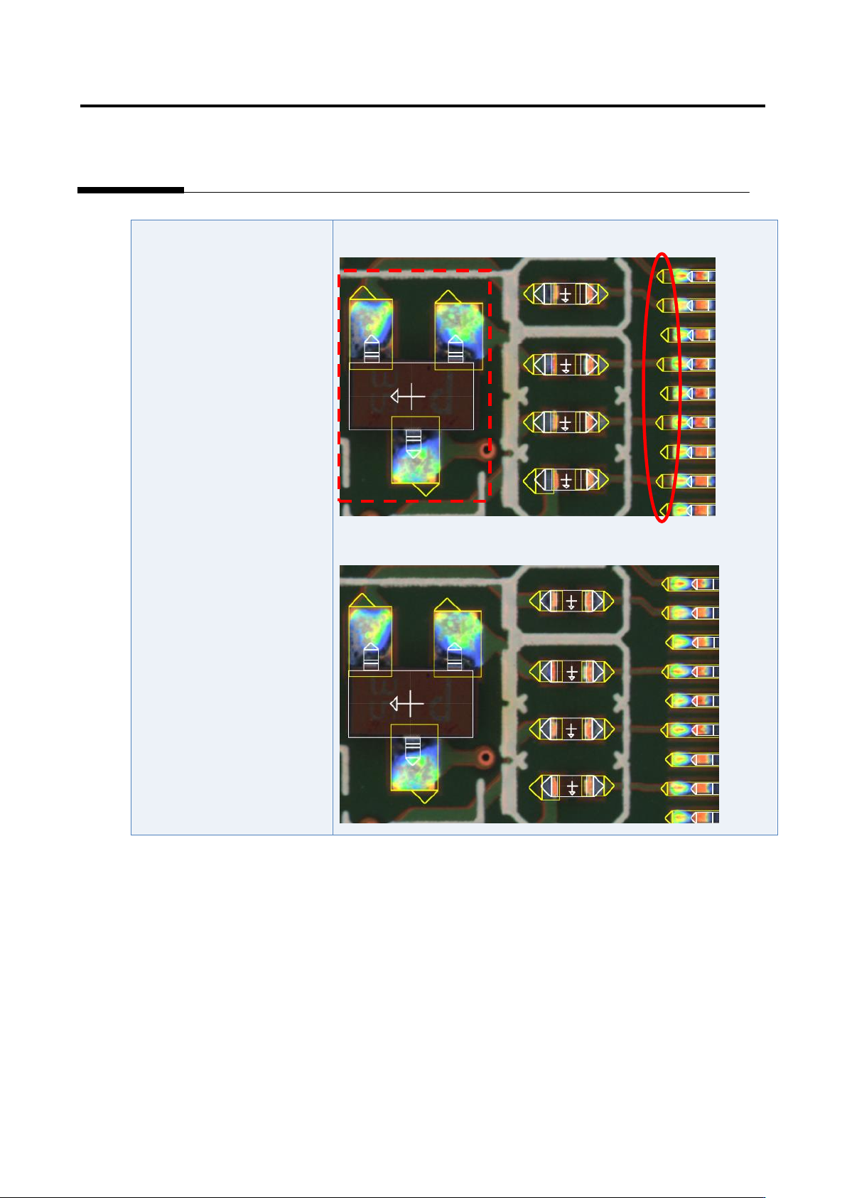
4) If not consistent, change the position or size of the land window.
Appendix 7. Position Correction/Extraction
a-18
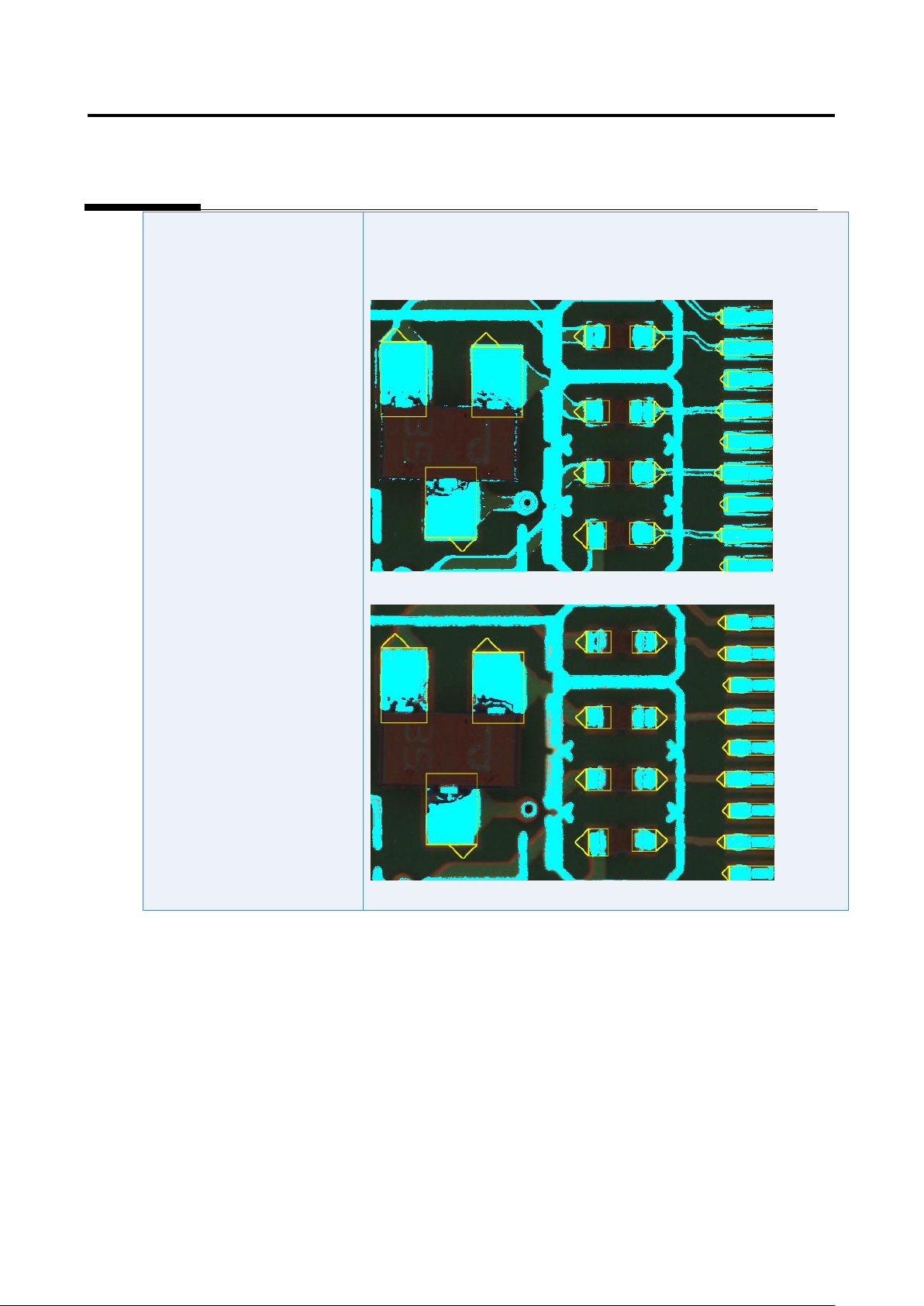
The position correction color
is not appropriate.
1) Select “Tool” - “PCB Image Management.”
2) Click the [Model Editing] button.
3) Confirm that the position correction color is set appropriately.
4) Change the color if not set appropriately.