Omron V-TS Teaching Manual.pdf.pdf - 第188页
2.15 M odifying an Inspection Pr ogram 2- 161 <Compone nt Number Group Sett ings Deploy ment Tool> The characteristic par ameters and inspect ion criteria of the selected component n umber group can be deplo yed to…

Chapter 2 Inspection Programming
2-160
(14) Clear All Button
Clicking this button sets OFF the characteristic parameters and all the Apply buttons of the
inspection criterion. If there are more than one electrode group, the Apply buttons of the
electrode group which is not being selected are not changed.
(15) Deploy All Inspection Criteria Button
When this button is clicked, all inspection settings are deployed to the component number
and electrode group of the deployment destination being selected without respect to
pressing the Apply button of the inspection setup section of the deployment source. Even the
items not displayed on the deployment screen are deployed. If there are more than one
electrode groups, criteria are deployed only for the effective electrode groups.
(16) Copy Button
Clicking this button deploys all the inspection settings with the Apply buttons being selected
from the source to the selected deployment target component number and electrode group.
(17) Close Button
Clicking the button closes the component number parameter deployment screen.
2.15 Modifying an Inspection Program
2-161
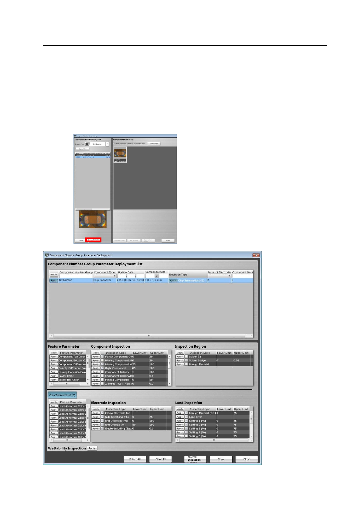
<Component Number Group Settings Deployment Tool>
The characteristic parameters and inspection criteria of the selected component number group
can be deployed to another component number.
On the component number group settings screen, click the [Deploy] button to open the
[Component Number Group Parameter Deployment] screen. The operation method of the screen
is equal to that of the component number settings deployment tool.
Chapter 2 Inspection Programming
2-162
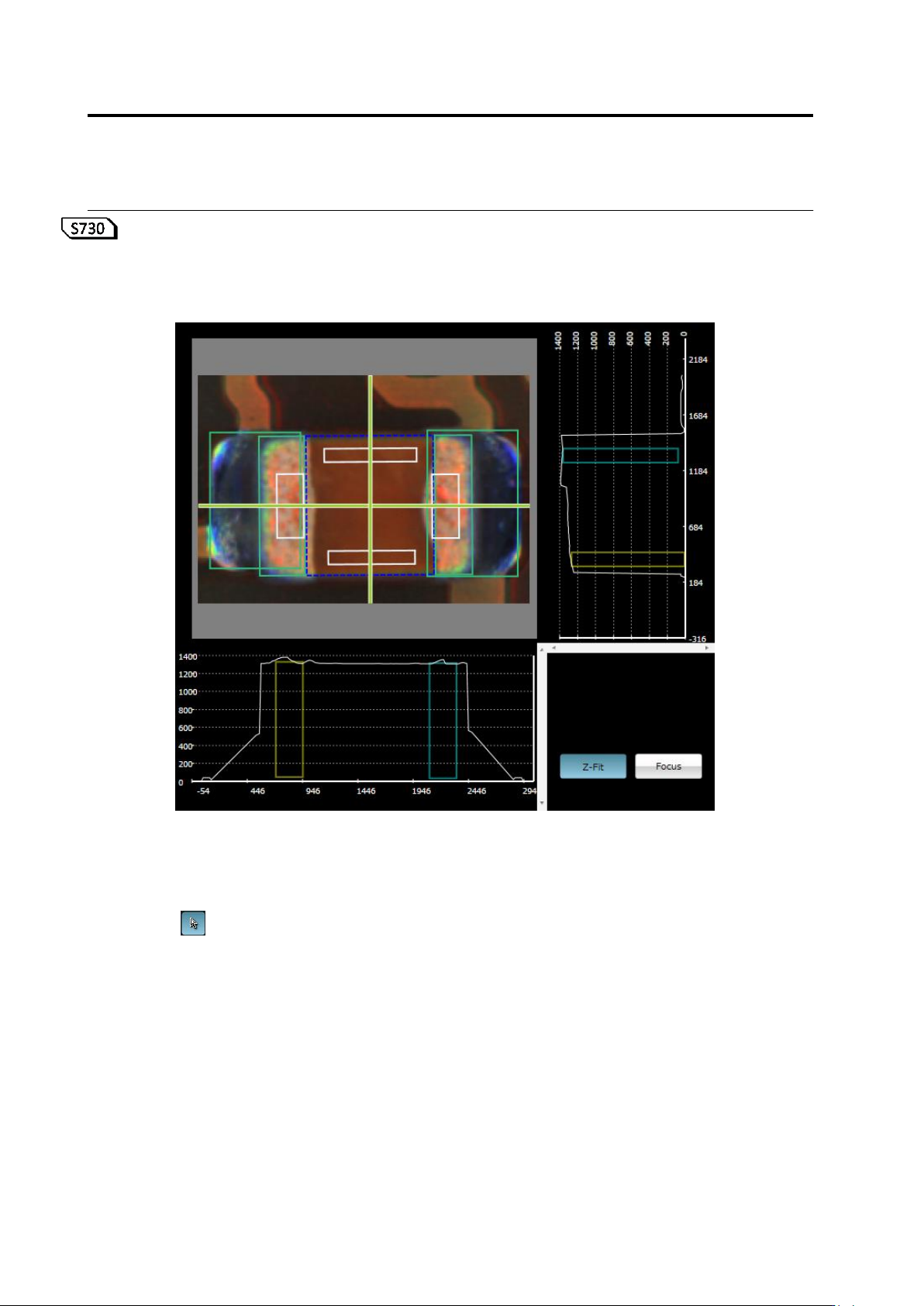
<Orthographic View>
If height measurement data is used for inspection, orthographic view appears.
Move the line profile to a location you want to check, and verify a component, component height,
and a fillet shape.
(1) X-Y Diagram
Displays a component thumbnail image.
(2) Line Profile Position Specification Line
Shows a slice position to display on X-Z and Y-Z diagrams.
If is set ON, you can move this by mouse dragging, cursor keys on the keyboard, or
left-clicking on the X-Y diagram while holding an Alt key.
The view is refreshed following the X-Y diagram view position and scaling.
⑤
⑥
(1)
(2)
(4)
(7)
(3)
(5)
(6)