Omron V-TS Teaching Manual.pdf.pdf - 第36页
2.1 Bas ics of Teach ing 2-9 Electrode Types This s y s tem provides i nspection in a specific way depending on the d efined electrode t ype. The types of electrode th at can be defined are determ ined according to the…
Chapter 2 Inspection Programming
2-8
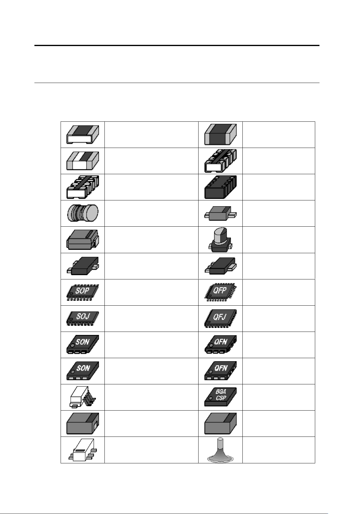
Component Types
This system classifies components under the following categories.
Component Type
Chip Resistor
Chip Capacitor
Other Chip Components
Resistor Array
(Micro-Lead)
Resistor Array (Castellated
Electrode)
Other Arrays (Non-Lead)
MELF Component
2 Pin Mini Mold Package
Inward L-Lead Package
Electrolytic Capacitor
Transistor
Power Transistor
SOP
QFP
SOJ
QFJ
SON (Micro-Lead)
QFN (Micro-Lead)
SON (Non-Lead)
QFN (Non-Lead)
Connector
BGA/CSP
Other Non-Lead Packages
Other Bottom Surface
Electrode Components
Other Lead Packages
Insertion Component
2.1 Basics of Teaching
2-9
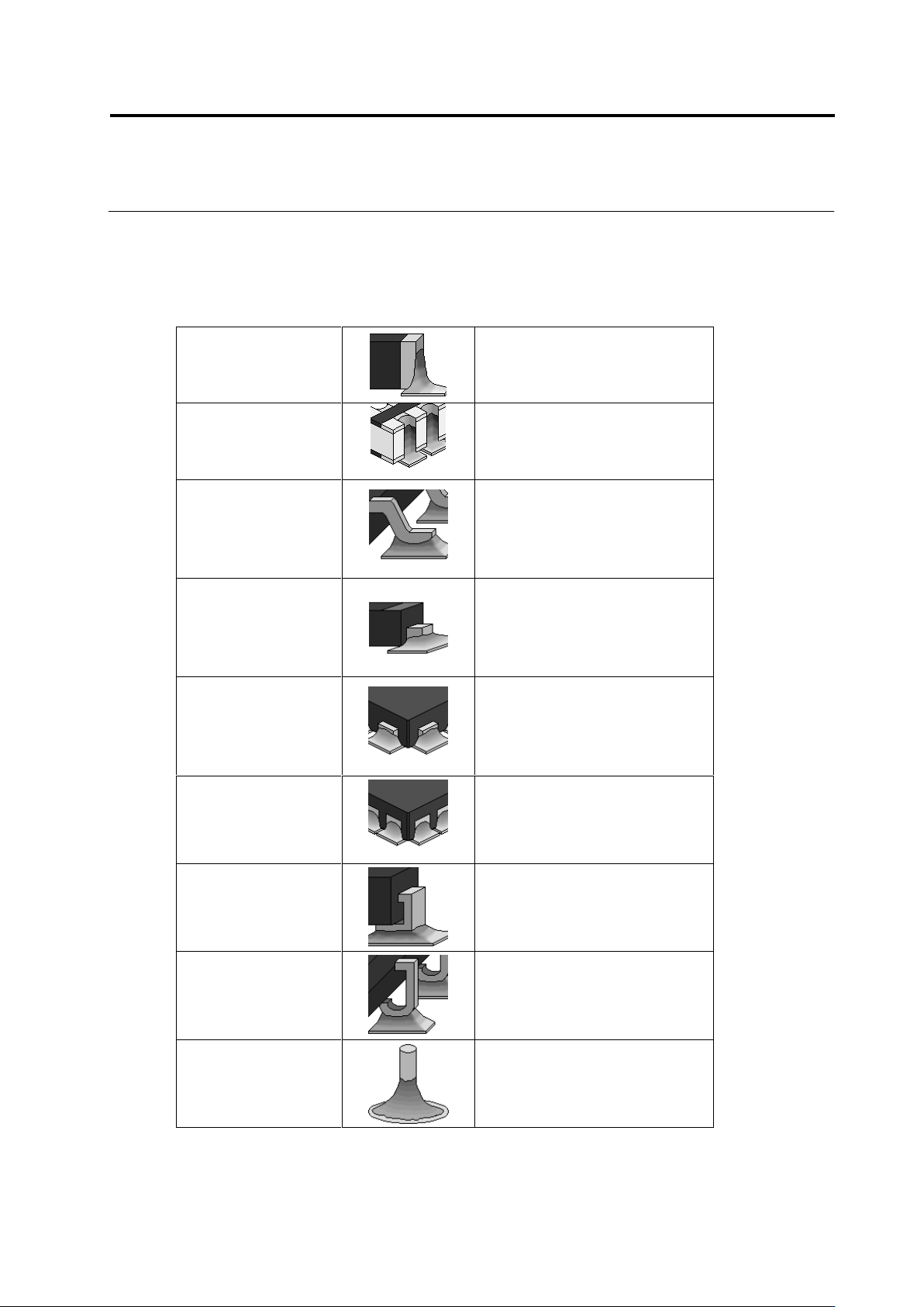
Electrode Types
This system provides inspection in a specific way depending on the defined electrode type.
The types of electrode that can be defined are determined according to the component types.
Electrode Type
Chip-Type Electrode
Chip Resistor
Chip Capacitor
Other Chip Components
MELF Component
Castellated Electrode
Resistor Array (Castellated
Electrode)
Gull-Wing Lead
2-Pin Mini-Mold Package
Transistor
Power Transistor
SOP, QFP
Connector
Other Lead Packages
Flat Lead
2-Pin Mini-Mold Package
Electrolytic Capacitor
Transistor
Power Transistor
Connector
Other Lead Packages
Micro-Lead
Resistor Array (Micro-Lead)
2-Pin Mini-Mold Package
Transistor
SON (Micro-Lead)
QFN (Micro-Lead)
Other Lead Packages
Non-Lead
Other Arrays (Non-Lead)
SON (Non-Lead)
QFN (Non-Lead)
Connector
Other Non-Lead Packages
Inward L-Lead
Inward L-Lead Package
J-Lead
SOJ
QFJ
Insertion Leads
Insertion Component
Chapter 2 Inspection Programming
2-10
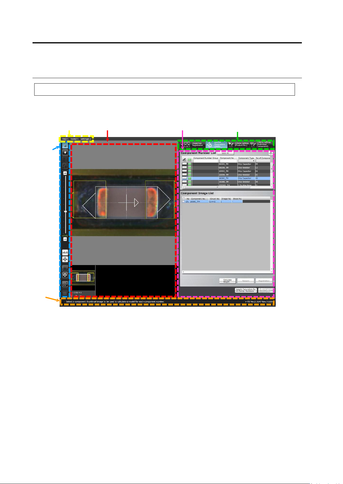
2.1.2 Configuration of the Editing Screen
The screenshot below shows the configuration of the Inspection Program Editing screen.
To view the editing screen, select a PCB you wish to edit from the inspection program list, and
click [Edit] in the bottom right corner of the screen.
(1) Menu Bar
Shows the following menu items:
・File Menu (Save, Save as Adjustment, Release, Recently Used Inspection Program, Reload,
Inspection Coverage, and Quit)
・Tool (PCB Image Management, Component Number Group Setting, Mass Production Image,
Move Component To Inspection Reference Position, Data Verification, Screen Brightness
Adjustment, Forced Lock Release, and Area Assistance)
・Setting (Set Inspection Program and Set Application)
(2) Status Display Area
Indicates the operation required on the currently displayed screen.
(1) Menu Bar
(3) Image Display Area
(6) Display Switch Tab
(5) Information Display Area
(4) Image
Operation
Buttons
(2) Status
Display Area