Omron V-TS Teaching Manual.pdf.pdf - 第15页
1-1 Chapter 1 Before Getting S t arted 1.1 Overview ............................................................. 1-2 1.1.1 Overview of T eaching S y st em ....................... 1 - 2 1.1.2 System Configuration .......…

13
Appendix 5. Real Fault Registration Procedure ........................................................................... 11
Appendix 6. Selection of Optimization Items ................................................................................13
Appendix 7. Position Correction/Extraction ..................................................................................14
Appendix 8. Height Information Setting ........................................................................................37
Appendix 9. Land Inspection Adjustment Procedure ...................................................................40
Appendix 10. Inspection Criteria Setting ......................................................................................61
Appendix 11. PCB Test Result Output Format .............................................................................63

1-1
Chapter
1 Before Getting Started
1.1 Overview ............................................................. 1-2
1.1.1 Overview of Teaching System ....................... 1-2
1.1.2 System Configuration .................................... 1-2
1.1.3 PC Specifications for v-TS ............................ 1-3
1.2 Basic Operations ................................................ 1-4
1.2.1 Using the Mouse ........................................... 1-4
1.2.2 Using the Keyboard ....................................... 1-6
1.3 Startup & Termination of the System .................. 1-7
1.3.1 System Startup .............................................. 1-7
1.3.2 System Termination ....................................... 1-8
1.4 Switching Languages ......................................... 1-9
1.5 Login and Logout .............................................. 1-10
1.5.1 Login ............................................................ 1-10
1.5.2 Logout ......................................................... 1-12
1.6 Menu Layouts ................................................... 1-13
Chapter 1 Before Getting Started
1-2
1.1 Overview
This section describes overview and configuration of the teaching system.
1.1.1 Overview of Teaching System
This system uses a PCB image captured by a PCB Inspection System to create and modify an
inspection program.
Improving an inspection program also improves an inspection pass rate of the PCB Inspection
System.
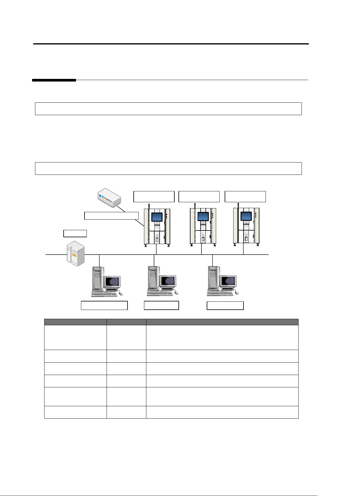
1.1.2 System Configuration
System Name
Abbreviation
Outline
PCB Inspection System
VT-S730
VT-S720A
VT-S500
VT-S730
VT-S720A
VT-S500
Main unit of the inspection system. It inspects a PCB and
captures a PCB image.
Teaching System
v-TS
TS
Creates an inspection program to be used and saves it to the
database.
Q-upNavi
Q-upNavi
Checks a production state and analyzes processes.
This can work on a PC that runs the teaching system.
Visual Check Assistant
v-CA
CA
Performs visual check based on an inspection result by the
system and saves the visual check result to the database.
Database
v-DB
DB
Stores inspection program creation information, inspection
results, and inspection system management information.
-
Upper-level system
-
Connection to an upper-level system is made through
RS-232C for transmission of PCB ID, etc.
PC for v-TS
PC for v-CA
PCB Inspection
System
PC for Q-upNavi
v-DB
Intranet
Upper-Level System
RS-232C
PCB Inspection
System
PCB Inspection
System