Omron V-TS Teaching Manual.pdf.pdf - 第167页
Chapter 2 Insp ection Progr amming 2- 140 (1) Feature Parameter Displa y W hen this checkbox is selected, the com ponent thum bnail image is binarized an d the extracted pixels using the c haracteristic param ete rs are …
2.15 Modifying an Inspection Program
2-139
Model Editing Screen Operation
When a logic selected on the inspection item column is changed with the model editing screen
open, the tools of the model editing screen are also changed.
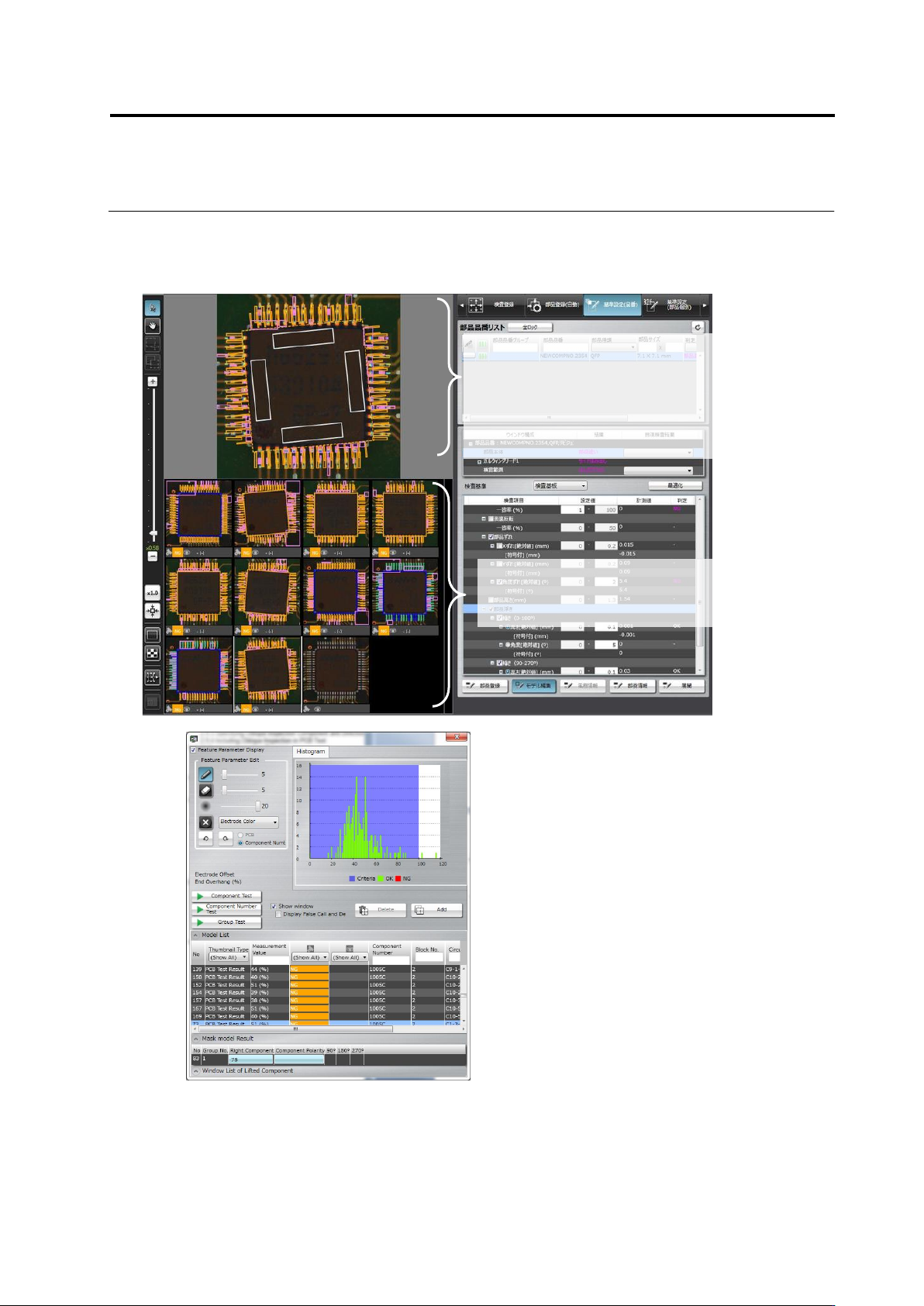
Shows a thumbnail list of the
component registered in the
library.
Displays a magnified view of the image
selected in the component thumbnail list
at the bottom of the screen.
Operate this component thumbnail to edit
the model.
(13)
(12)
(3)
(4)
(5)
(6)
(7)
(8)
(9)
(10)
(12)
(1) ①
(2)
(11)
Chapter 2 Inspection Programming
2-140
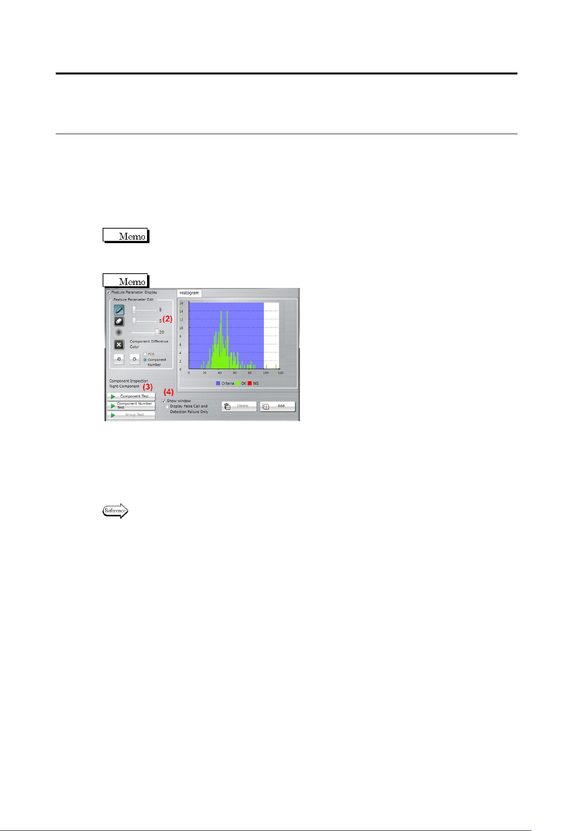
(1) Feature Parameter Display
When this checkbox is selected, the component thumbnail image is binarized and the
extracted pixels using the characteristic parameters are displayed in aqua color.
For component extraction or component presence, two or more characteristic parameters
can be displayed simultaneously.Select the display item from [Show All Colors] or [Show
Selected Colors]. If [Show All Colors] is selected for component extraction, the component
top color is displayed in yellow, and electrode color, in aqua.
Binarization refers to the process of converting individual pixels into binary values based
on a brightness threshold, in which pixels equal to or below the threshold value is
represented in "0" and those above the threshold value, in "1". In TS, "0" values are
displayed in aqua color.
The checkbox is selected by default.
(2) Feature Parameter Edit
Displays the characteristic parameters editing tool.
The tool is consisted the following two types:
・Color Table Editing Tool … For characteristic parameters other than character and mark
colors
・Model Image Editing Tool … For are (color), shape (brightness), and shape (color)
Refer to <Color Table Editing Tools> or <Model Image Editing Tools> of 2.15.3 “Editing a Model”
of for the procedures to operate individual editing tools.
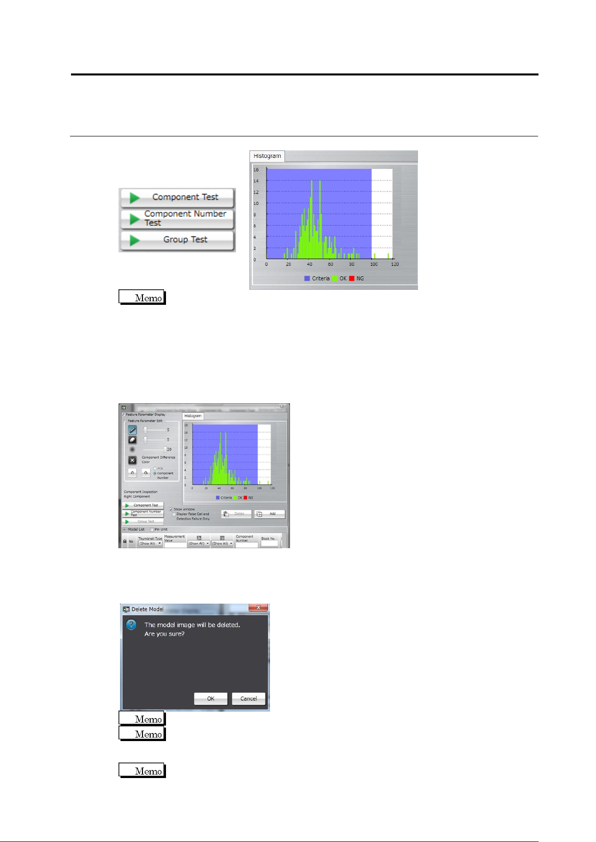
(3) Test
Test the component thumbnail images with the edited characteristic parameters. After
testing, the measured value and judgement result for the individual component thumbnails,
as well as the histogram of all the measured values are displayed.
[Component Test]: Test is performed only for the selected component.
[Component Number Test]: Test is performed for all images of the selected component
number.
[Group Test]: Test is performed for all images of the component number group to which the
selected component number belongs.
2.15 Modifying an Inspection Program
2-141
The Model Editing screen shows the measured values, judgment result, and histogram of
PCB testing when it is opened after the test. However, the result of oblique inspection is
not displayed. Perform a test to check the result.
(4) Show Window (Display False Call and Undetected Fault only)
- Show Window: Switches a view of window detection position detected by the test.
Selecting/unselecting this option shows/hides the window, respectively.
- Display False Call and Undetected Fault only: Inspection result is displayed only in the
case of false call or undetected fault.
(5) Delete/Add
Deletes/Adds the model image selected in the component thumbnail list.
Click the [Delete] button. The delete confirmation dialog appears. Click [OK] to delete the
image.
The [Delete] button is not effective if an image other than a model image is selected.
The [Delete] button is also disabled when only one model image is in the component
number.
Click the [Add] button to register the selected image as a model.
The [Add] button is disabled if a model image is selected.
(5)
(7)
(6)