Omron V-TS Teaching Manual.pdf.pdf - 第98页
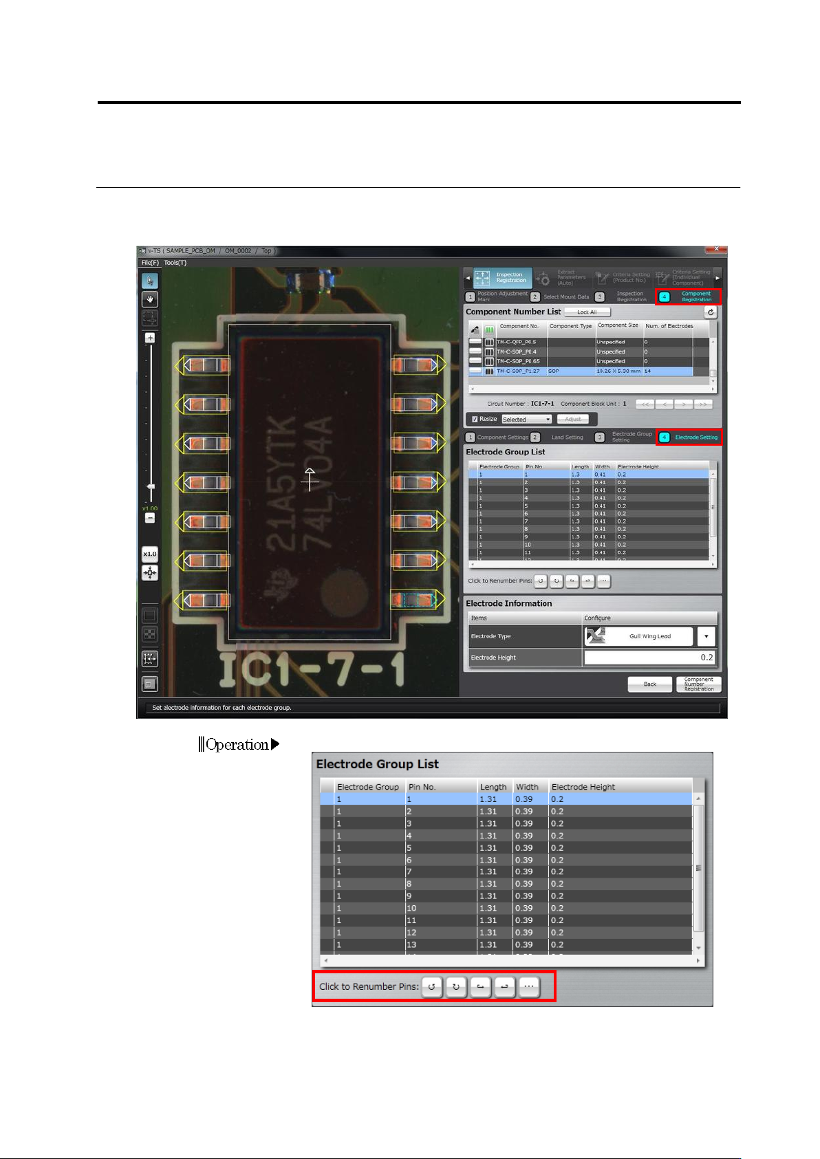
2.4 Registeri ng f or Insp ection 2- 71 2.4.5.4 Electrode Setting S et a pin num ber , electrode t ype or height f or each electrode gr oup. 1. Set a pin num ber if neces sary.
Chapter 2 Inspection Programming
2-70
3.
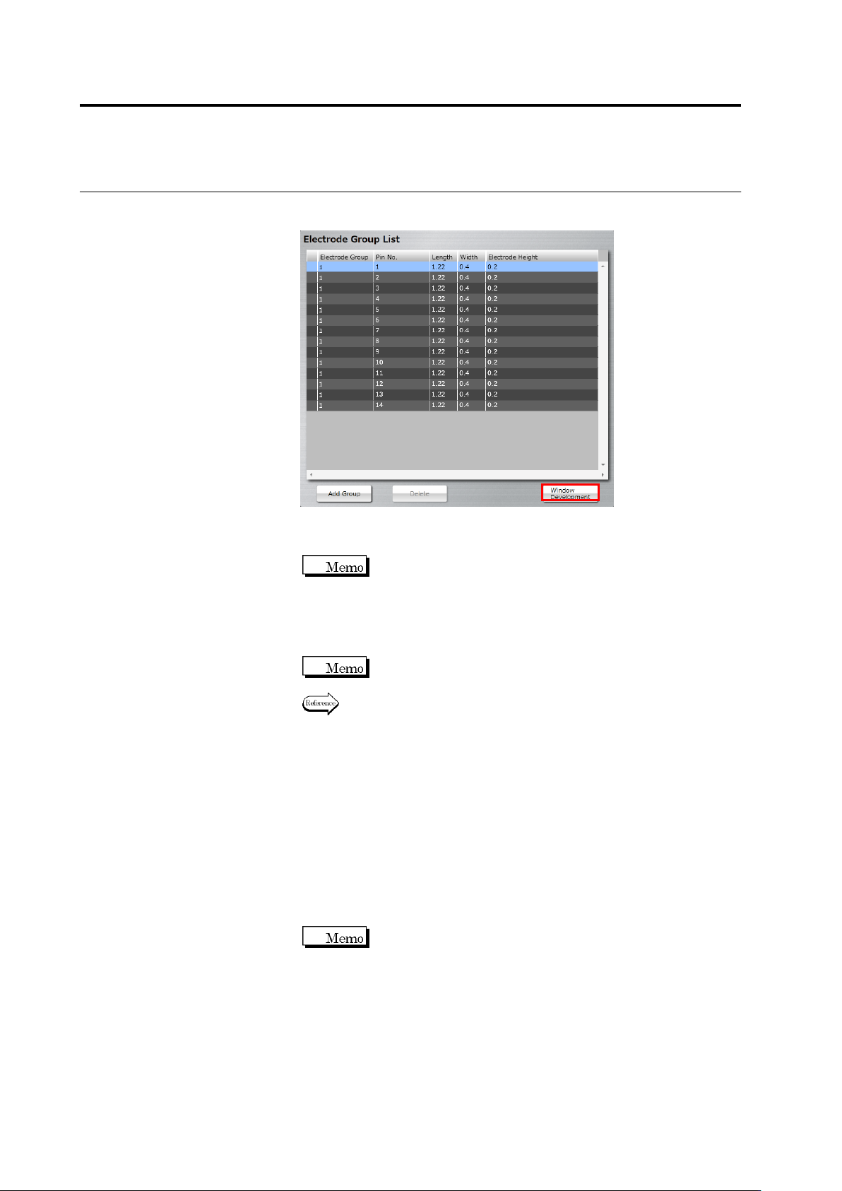
Select the electrode window drawn in Step 2, click [Window
Development].
Windows of the same size as the selected electrode window are
positioned on the electrodes in the same group.
When the positions of the land window and electrode window
are not correct (land window is in red), the [Window
Development] button is disabled.
4.
Select an individual electrode window to adjust the position and
size.
When an electrode window is resized, other electrode windows
in the same group are also resized.
Refer to "2.1.3 Image Display Area Operation" for the image
display area operation.
5.
Perform Step 2 to 4 for each electrode group.
6.
When modifying the land window after setting the electrode window,
click [Back] to return to the land settings screen, modify the land
window and then click [Next]. When mismatch between the
electrode window and land window occurs (deleting a land, etc.),
the [Delete] button is enabled. When you click [Delete], all the
electrode windows are deleted. Perform operation from Step 1
again.
7.
Click [Next] to proceed to the Electrode Setting screen.
The [Next] button will be enabled when you set electrode
windows to all the land windows.
Chapter 2 Inspection Programming
2-72
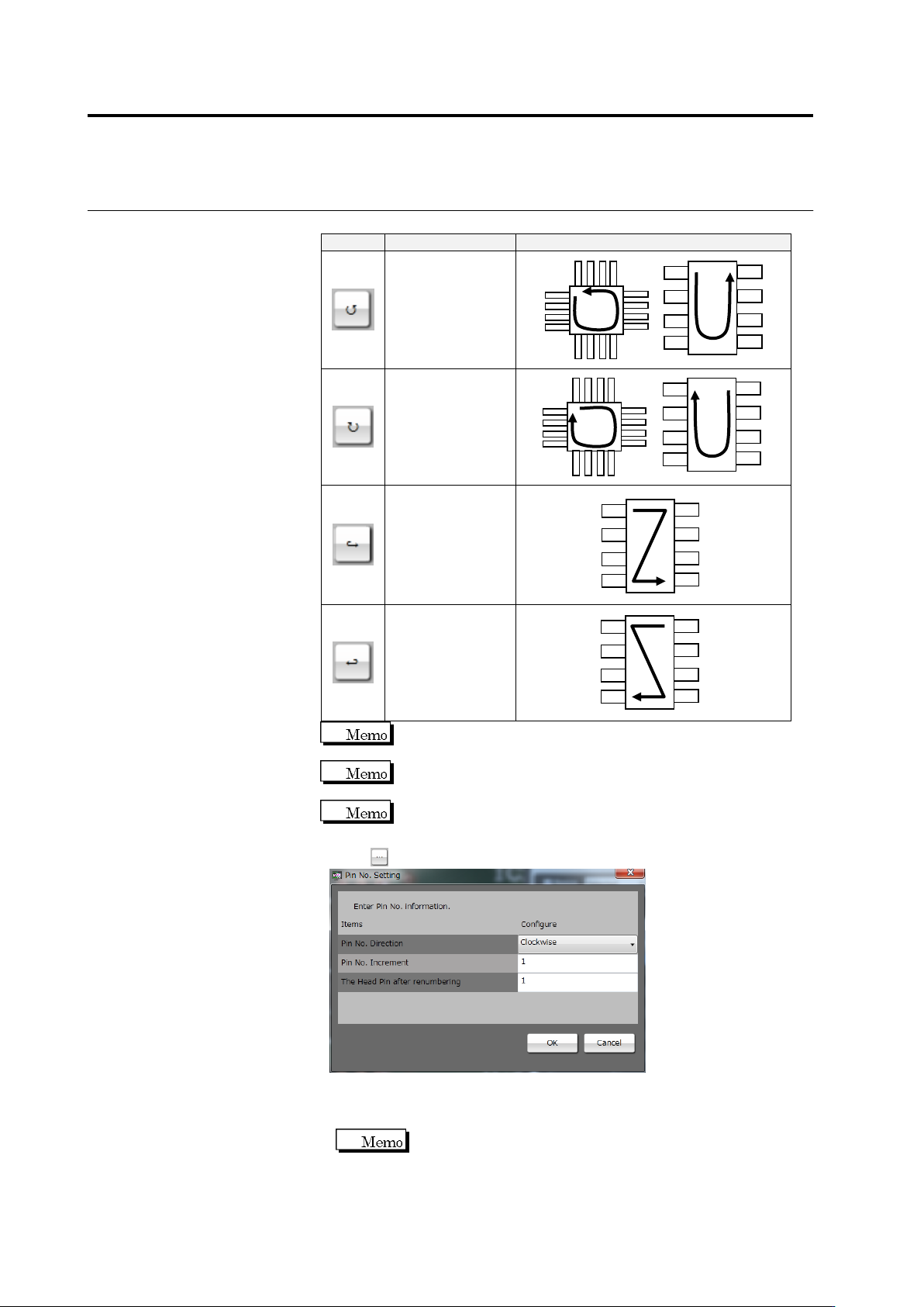
Select a pin number increment direction from the options below:
Button
Direction
Pin Numbering Example
Counterclockwise
Clockwise
From Left to Right
From Right to Left
The currently selected pin is numbered "1" in the
counterclockwise or clockwise direction.
The top left pin and top right pin are numbered "1" in the left to
right direction and right to left direction, respectively.
The left to right and right to left directions are only effective for
components such as SOPs with electrodes on both sides.
Click to change the pin numbers.
◆ Pin No. Direction: Select one of the four options above.
◆ Pin No. Increment: Enter an increment of the pin number.
◆ The Head Pin after renumbering: Enter a pin number set on pin 1.
This item can only be specified only when the pin number
direction is clockwise or counterclockwise.
Click [OK] to apply the setting.