Omron V-TS Teaching Manual.pdf.pdf - 第191页
Chapter 2 Insp ection Progr amming 2- 164 (7) Lifted Component W indow A window to inspect c omponent height an d lifted com ponent is displayed on t he X -Y diagram as a white fram e. A lifted com ponent window area is …
2.15 Modifying an Inspection Program
2-163
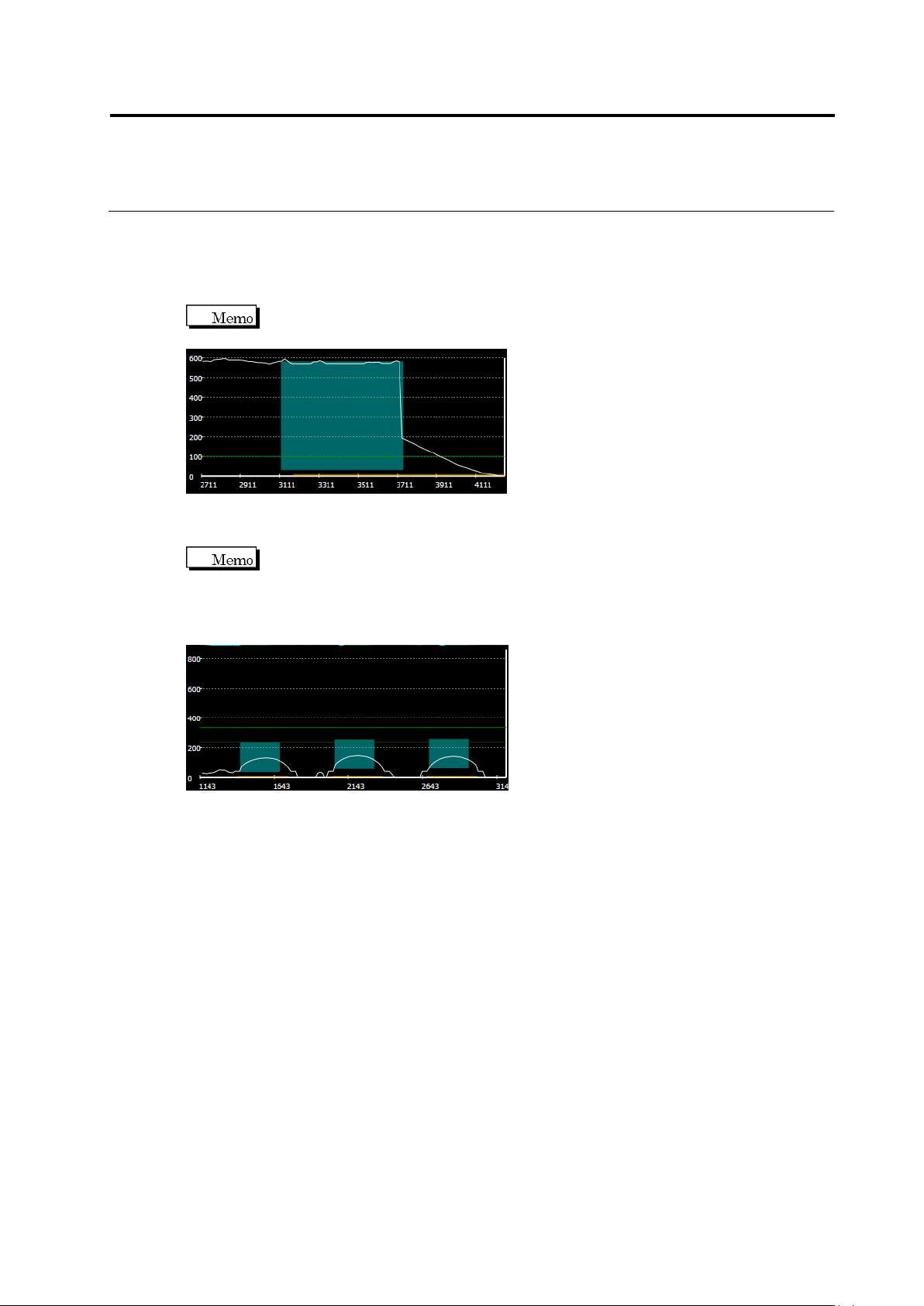
(3) X-Z Diagram
Displays the following slice information of X-Z.
Slice Height: White line
Electrode Position/Height: Light blue paint-out frame (displayed when fillet inspection,
electrode lifting, or coplanarity is selected)
If fillet inspection is selected, the electrode being selected is displayed as a light
blue paint-out frame.
Lifted Component Inspection Criteria: Green line (displayed when component lifting
or coplanarity is selected)
If coplanarity is selected, all the electrodes belonging to the electrode group
being selected are displayed as light blue paint-out frame. A green line is displayed at the
height of the lowest electrode, and the other green line is displayed at the height which is the
height of the inspection criterion above the former green line. The range of OK products for
coplanarity inspection is between these two lines.
(4) Y-Z Diagram
Displays the slice information of Y-Z. The details are the same as that of X-Z diagram.
(5) Z Scale Adjustment Toggle Button
Setting the button ON scales the Z axis so as to fit in the screen.
Setting the button OFF displays the Z axis in the same scale as X and Y.
(6) Window Centering Button
Clicking the button adjust the position of the selected window to the center of the X-Y
screen.
Chapter 2 Inspection Programming
2-164
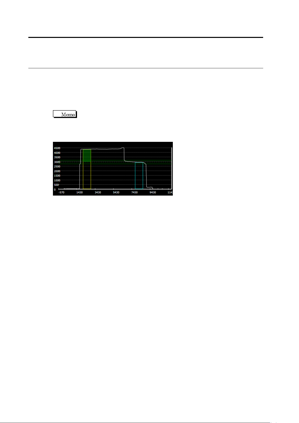
(7) Lifted Component Window
A window to inspect component height and lifted component is displayed on the X-Y diagram
as a white frame.
A lifted component window area is displayed in the X-Z and Y-Z diagrams.
When an incline of 0-180° or 90-270° is selected, the yellow and light blue frames indicate
the reference point and measurement point, respectively. If neither range is selected, the
window is displayed in gray.
To the yellow frame of the reference point, the height of the preset unevenness
is displayed as a green paint-out frame. The green reference point is displayed in the
position which is the height of the unevenness above the top of the yellow frame of the
reference point. The green dotted line indicates the center of the reference, and the green
solid line indicates the upper and lower limits of the inspection settings, respectively.
2.15 Modifying an Inspection Program
2-165
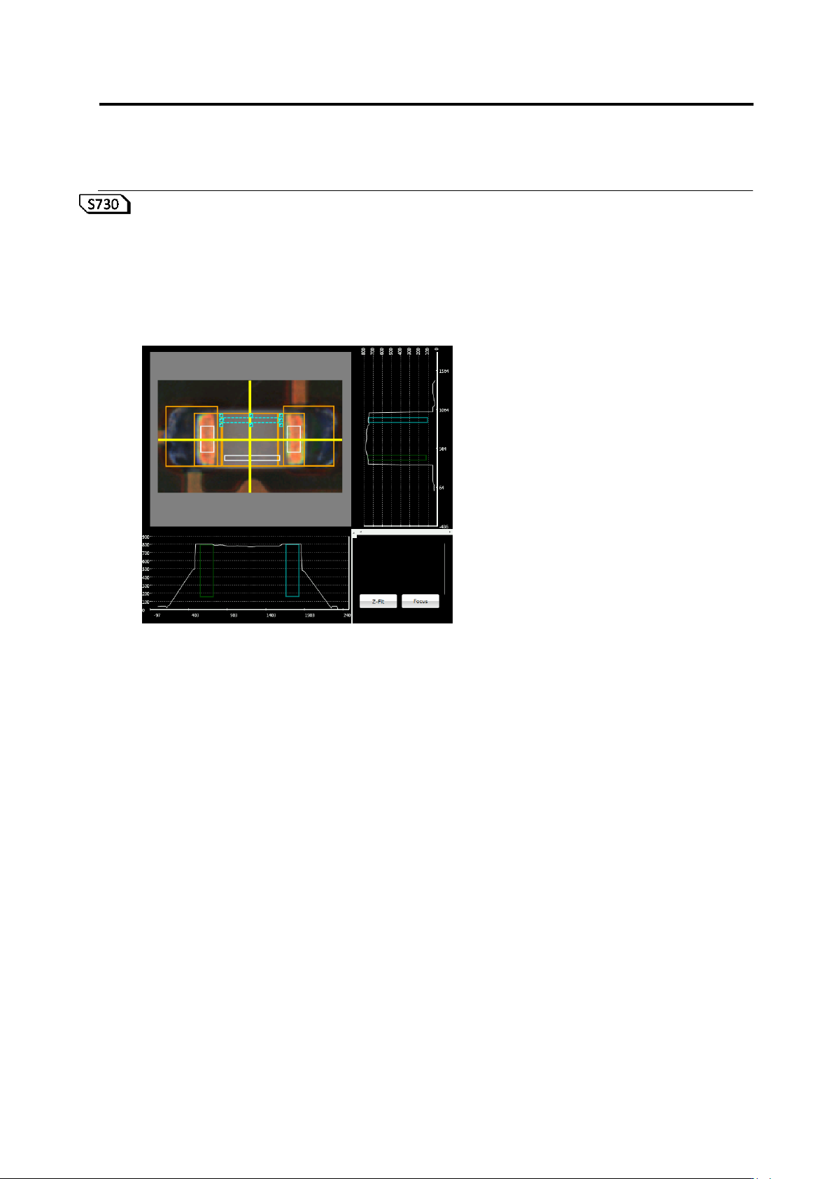
<Lifted Component Inspection Editing Tools>
If the component height/lifted component inspection is being selected, the lifted component
inspection editing tools are displayed.
If the component height or lifted component (average height) is being selected, the lifted
component window is displayed in a white frame on top of the component. Inspect component
height/lifting by editing the position and/or size of the lifted component window.
(1)