Omron V-TS Teaching Manual.pdf.pdf - 第75页
Chapter 2 Inspecti on Programm ing 2- 48 The upper/lower reverse button and the r ight/left reverse button operate as follows: Right/ left reverse Upper/lower reverse Upper/ lower reverse The component coordin ates are r…
2.4 Registering for Inspection
2-47
◆
Adjustment Using the Mouse
Click the Select Window button in the Mouse toolbar and drag the
mount data to align the "+" marks to the centers of corresponding
components.
◆
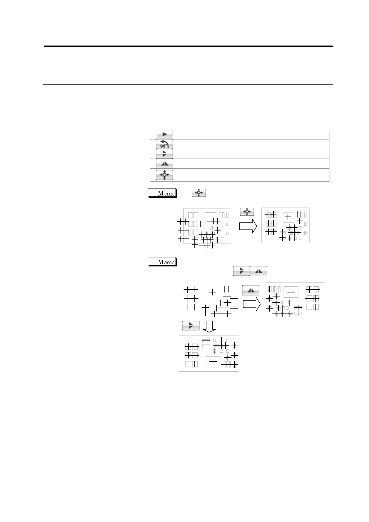
Adjustment Using Buttons
Move the mount data in the arrow direction.
Rotate the mount data by 90 degrees counterclockwise.
Vertically reverse the mount data.
Horizontally reverse the mount data.
Align the center of the mount data at the center of the
PCB image.
Use to align the centers of the mount data and PCB
image if the position deviation is large.
If the mount data uses a different coordinate system from
the PCB image, click to reverse the mount
positions before position alignment.
Chapter 2 Inspection Programming
2-48
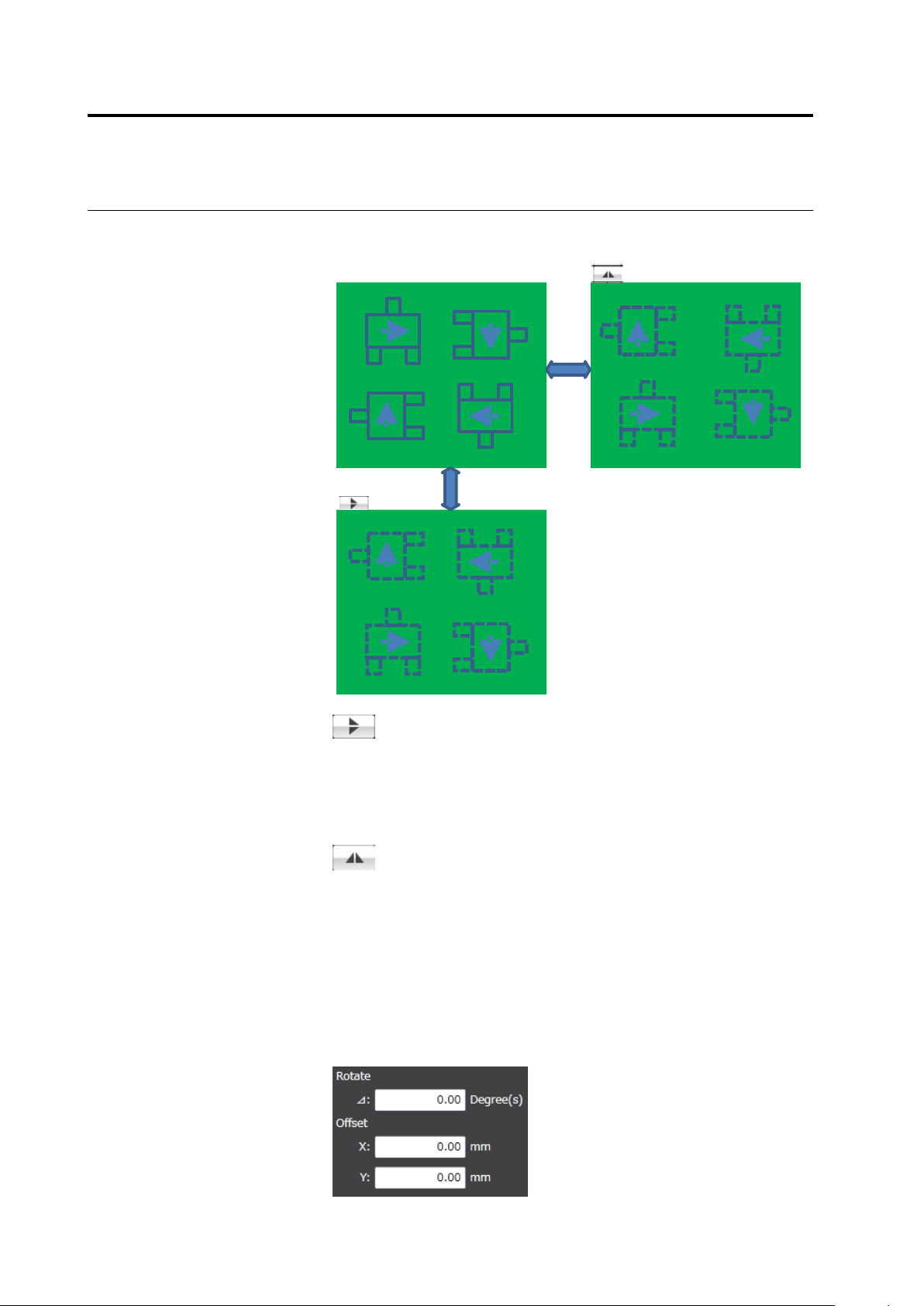
The upper/lower reverse button and the right/left reverse button
operate as follows:
Right/left reverse
Upper/lower
reverse
Upper/lower reverse
The component coordinates are relocated vertically by line
symmetry. The angle of each component is not converted.
It is assumed that the mount data are kept with the
components on the back of the PCB permeating the PCB
and the angles of them are correct.
Right/left reverse
The component coordinates are relocated horizontally by
line symmetry. The angle of each component is rotated at
180 degrees.
It is assumed that the mount data are kep with the
components on the back of the PCB permeating the PCB
and the angles of them are correct.
◆
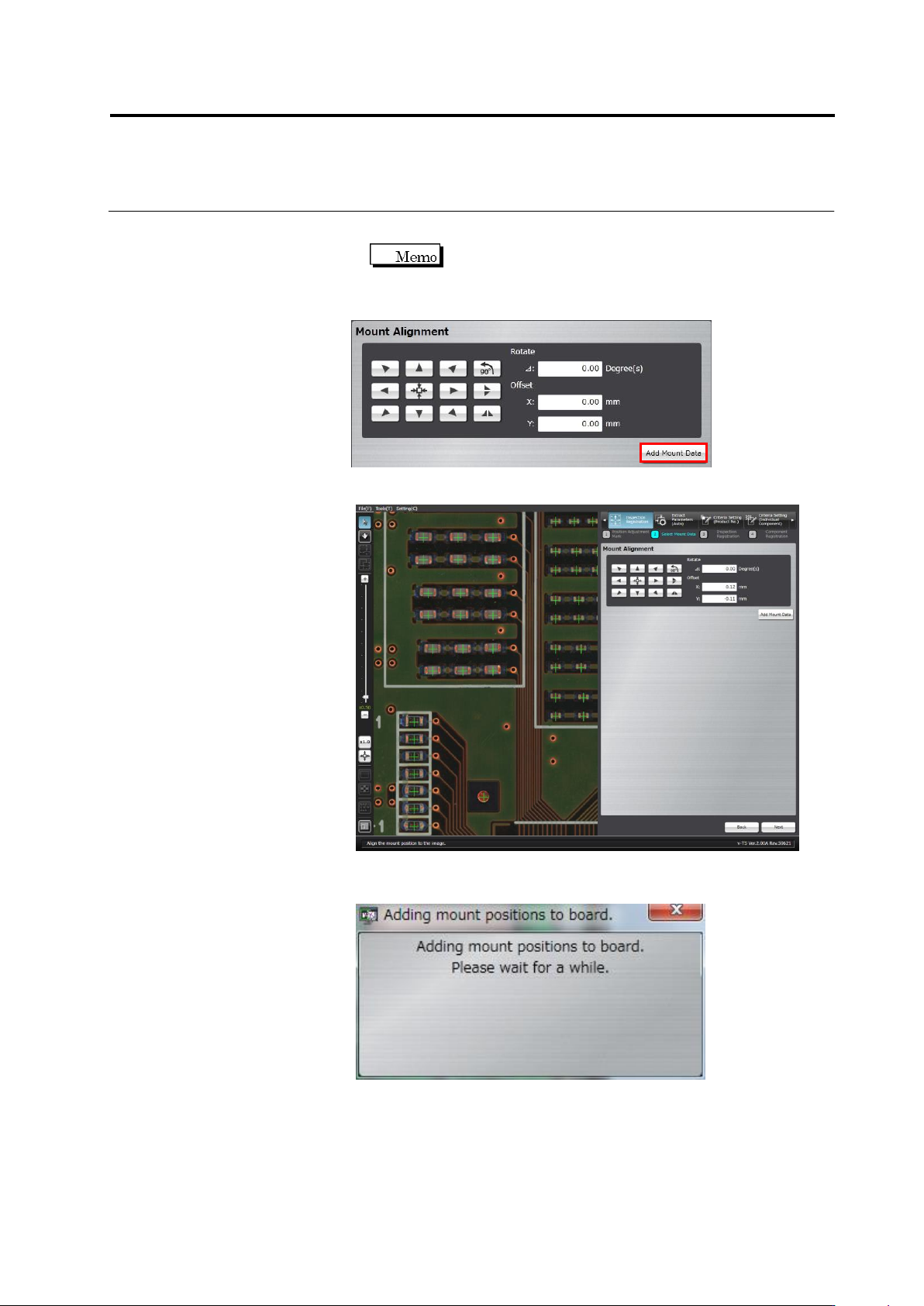
Adjustment by Inputting Values
The rotation angle and offset values obtained by the mouse or
button operation are shown in the screen. Edit the angle and X and
Y coordinate values directly for fine tuning.
2.4 Registering for Inspection
2-49
Up to two decimal places can be entered for the rotation
angle and offset values.
2.
Click [Add Mount Data] to add more mount data and repeat Step 1.
3.
Click [Next].
The mount position addition processing dialog appears. After
processing, the screen returns to the inspection registration screen.