Omron V-TS Teaching Manual.pdf.pdf - 第295页
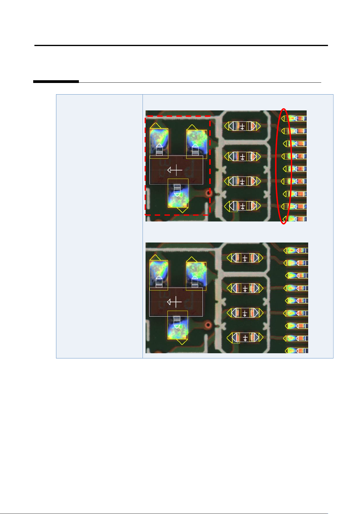
Appendix 7. Positio n Correction/Extractio n a- 18 The position correction color is not appropriate. 1) Select “T ool” - “PCB Im age Management.” 2) Click the [M odel Editing] b utton. 3) Confirm that the position correc…
Appendix 7. Position Correction/Extraction
a-17
4) If not consistent, change the position or size of the land window.
Appendix 7. Position Correction/Extraction
a-18
The position correction color
is not appropriate.
1) Select “Tool” - “PCB Image Management.”
2) Click the [Model Editing] button.
3) Confirm that the position correction color is set appropriately.
4) Change the color if not set appropriately.

Appendix 7. Position Correction/Extraction
a-19
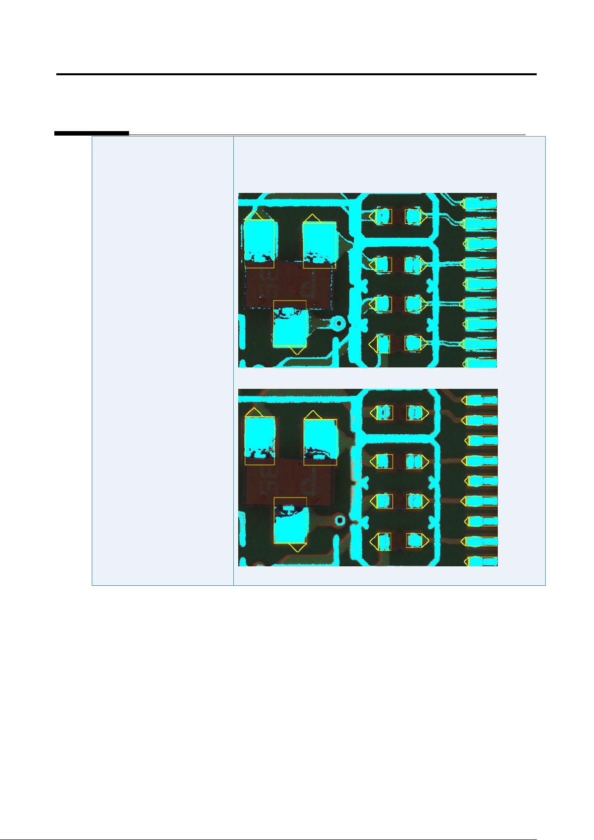
3. Extraction offset confirmation procedure
After conducting a PCB test using an adjustment image, whether the extraction offset occurs or not on
the component number (component number group) in which an inspection fault has occurred is verified
based on the shape of the histogram of the model editing screen according to the following inspection
items.
When the extraction offset occurs, refer to the component extraction procedure and the
component tip extraction procedure of appendix section 5 and 7, respectively to adjust to
eliminate extraction offset.
Comp. type
Condition
Inspection item to select
Judgment criteria for no
skew
Chip component
Electrode
capacitor
Transistor
Powered
transistor
2-pin mini mold
Non-lead
component
Other component
applicable to the
conditions on the
right
Component whose
width is at least 120%
or no electrode for the
electrode width
For the component body
window:
- Component offset –
Offset X [Absolute
value]
- Component offset –
Offset Y [Absolute
value]
All the measured
values of good
components must be
within the default
inspection criteria.
IC
Connector
Resistor array
The width of the land
for the electrode width
is less than 120%.
Electrode window:
- Side overhang
- End overhang
The distribution width of
the measured value of
the good component
must be 20% or less.
Example 1: Verifying extraction offset of 2-pin mini mold
On the left figure, the values are within the inspection criteria so it is judged as no offset. On the center
and right figures the values are not within the inspection criteria so they are judged as offset.