Omron V-TS Teaching Manual.pdf.pdf - 第307页
Appendix 7. Positio n Correction/Extractio n a- 30 6. Electrode side extraction Inspection result Component im age (PCB test) Cause Confirm ation and repair method Electrode s ide extrac tion is not aligned. 1) Move to t…
Appendix 7. Position Correction/Extraction
a-29
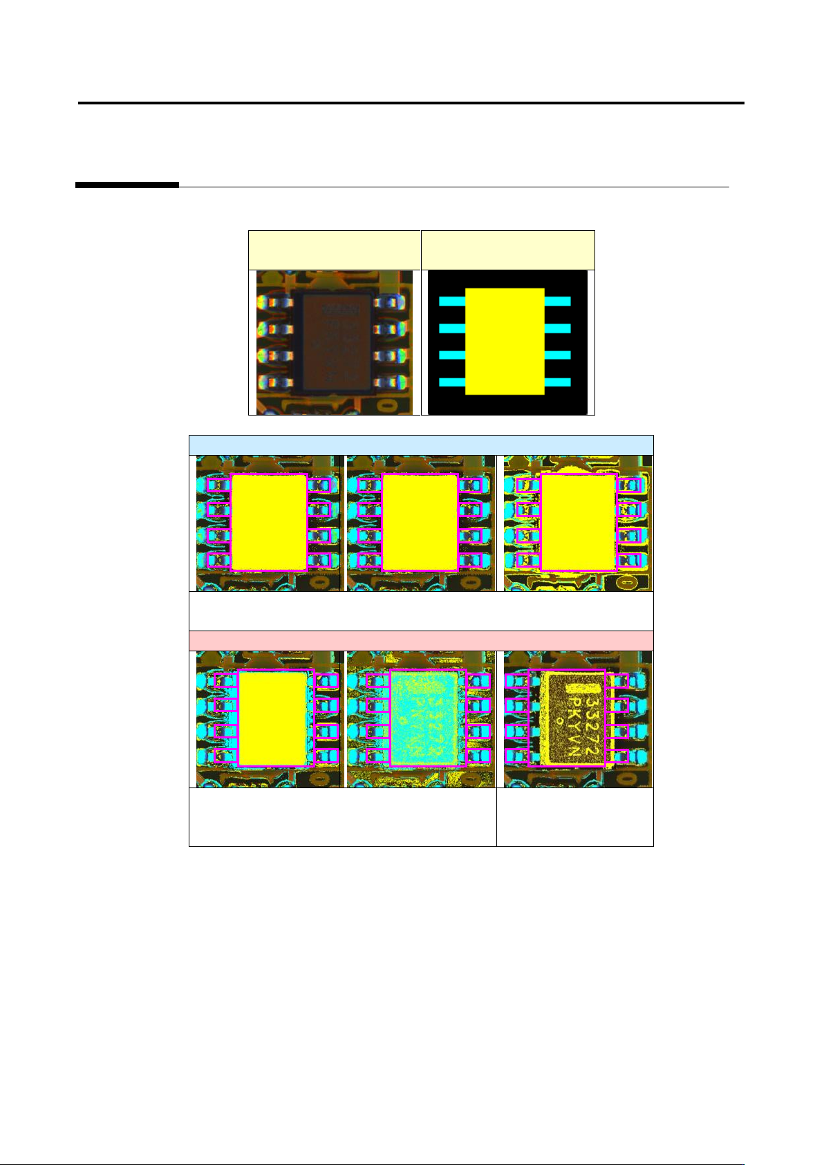
Example 3. SOP
Inspection image
Component extraction
model
Acceptable
All the conditions from (1) to (5) are satisfied and therefore
component extraction succeeds.
Unacceptable
Component extraction fails because condition
(5) is not satisfied.
Component extraction
fails because condition
(1) is not satisfied
Appendix 7. Position Correction/Extraction
a-30
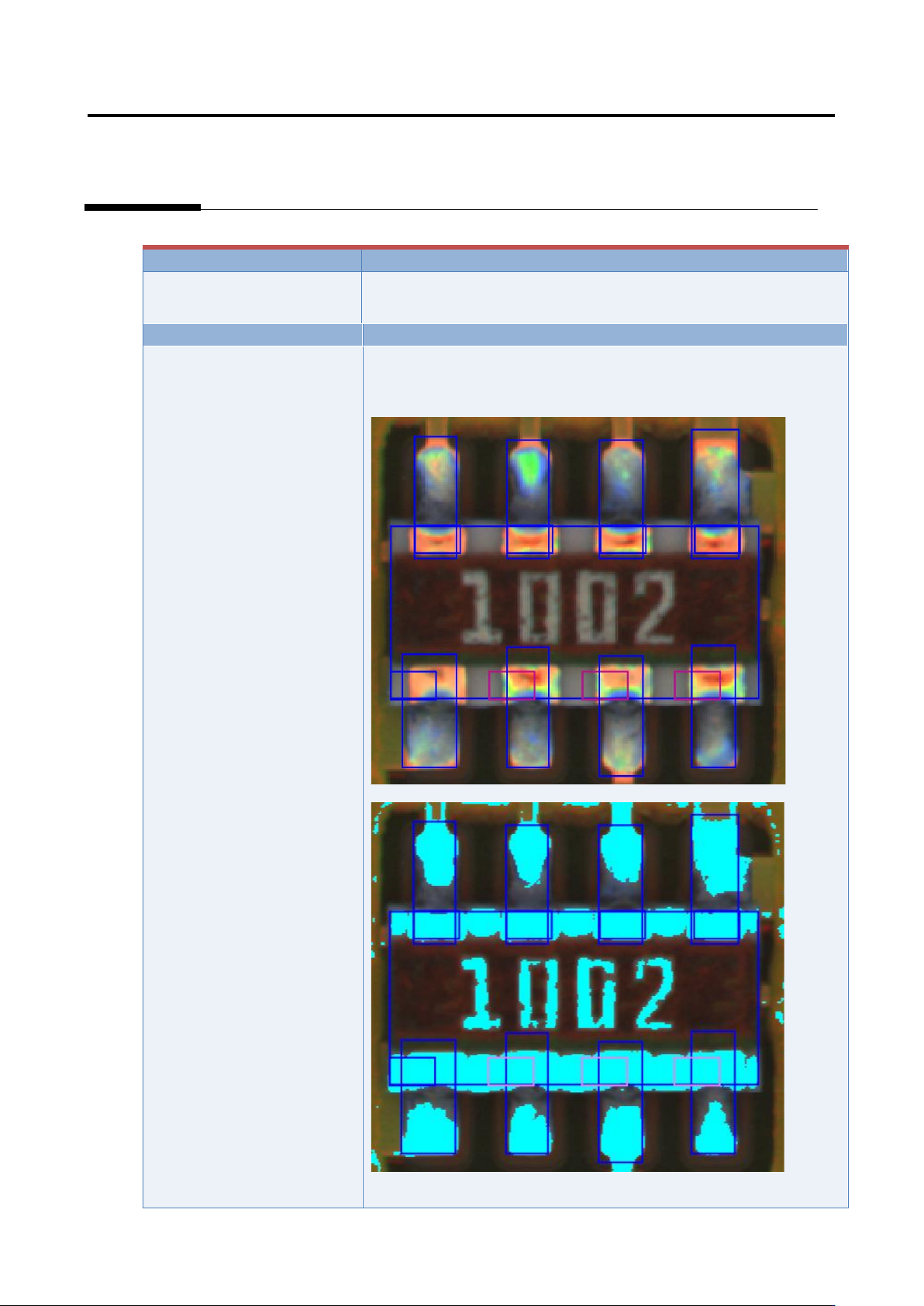
6. Electrode side extraction
Inspection result
Component image (PCB test)
Cause
Confirmation and repair method
Electrode side extraction is
not aligned.
1) Move to the “Criteria Setting” tab.
2) Select “Inspection Criteria” - “Electrode Side Extraction,” and
click the [Model Editing] button.
3) Confirm if the electrode color is being set.
4) Set the electrode color if not being set.
Appendix 7. Position Correction/Extraction
a-31
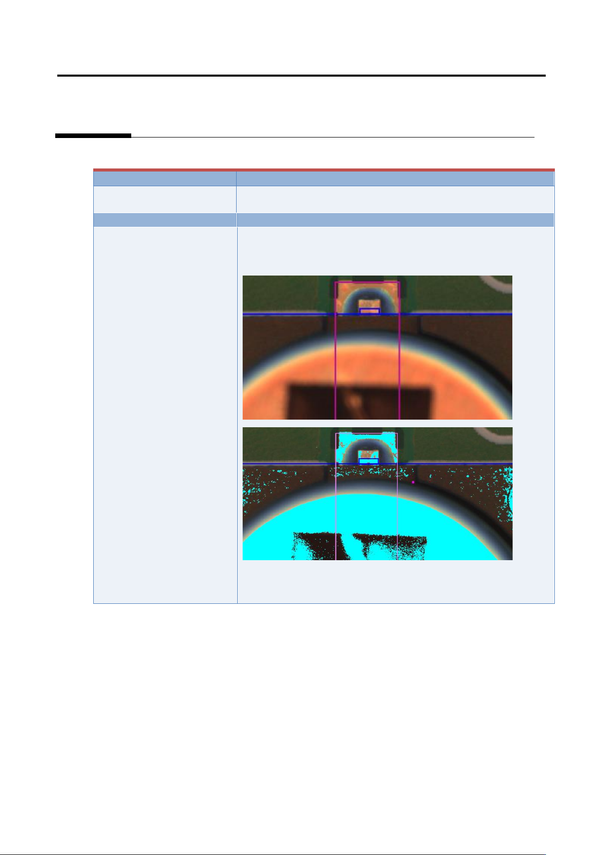
7. Electrode Tip Extraction
Inspection result
Component image (PCB test)
Cause
Confirmation and repair method
Electrode tip extraction is not
aligned.
1) Move to the “Criteria Setting” tab.
2) Select “Inspection Criteria” - “Electrode Tip Extraction,” and
click the [Model Editing] button.
3) Confirm if the electrode color is being set.
4) Set the electrode color if not being set.
(*Image to be pasted)