Omron V-TS Teaching Manual.pdf.pdf - 第196页
2.15 M odifying an Inspection Pr ogram 2- 169 2.15.4 Optimizing Boolean Expressions and Inspection Criterion Values Inspection cr iterion values are opt imized based on the v isual check result i nformat ion registered f…
Chapter 2 Inspection Programming
2-168
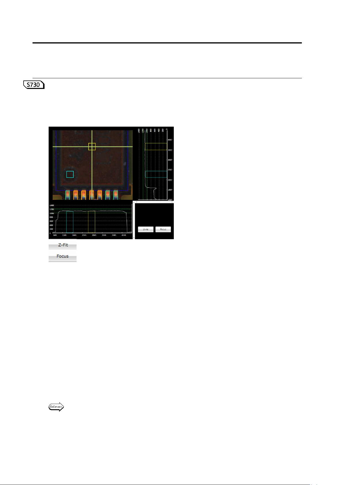
<Wrong Polarity/Height Inspection Edit Tool>
If wrong polarity/height inspection is being selected, the comparison area (reference point:
yellow) and polarity mark area (measurement point: light blue) are displayed in the wrong
polarity/height inspection edit tool. You can edit a position and/or size of the comparison and/or
polarity mark area to perform wrong polarity/height inspection.
: Z scale is extended based on the maximum height value.
: The selected window is displayed.
<Target Component (Recommended)>
- Other Chip:
An LED level difference is detected and the polarity inspection is performed.
- SOP, QFP, SOJ, QFJ, SON, QFN, connector, other lead component, other non-lead component,
other bottom electrode component, CSP, BGA
An embossed mark is detected and the wrong polarity inspection is performed.
① Comparison area (reference point: yellow)
Specify a measurement range of height information used for the wrong polarity/height
inspection. Use the mouse to edit the window position and size.
In X-Y, X-Z, and Y-Z diagrams, reference point window position (yellow rectangle) and
measured value of the reference point height are indicated as dashed lines and upper and
lower limits of the inspection criteria as continuous line.
② Polarity mark area (measurement point: light blue)
Specify a measurement range of height information used for the wrong polarity/height
inspection. Use the mouse to edit the window position and size.
In X-Y, X-Z, and Y-Z diagrams, measurement point window position (light blue rectangle) is
indicated.
For details of the inspection criteria and process, see Inspection Logic Manual, "3.4 Wrong
Polarity/Height".
①
②
2.15 Modifying an Inspection Program
2-169
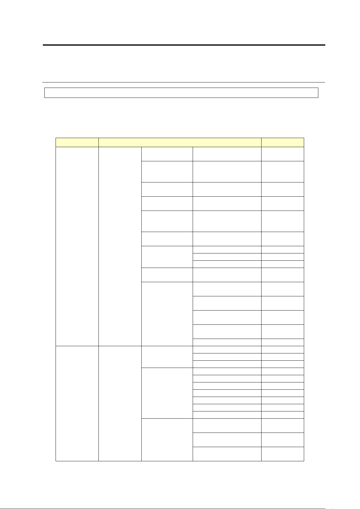
2.15.4 Optimizing Boolean Expressions and Inspection Criterion Values
Inspection criterion values are optimized based on the visual check result information
registered for each inspection window of model images. Optimization can reduce
missing/excessive detection of errors.
Inspection items that can be optimized
Window Type
Inspection Item
Optimization
Component
Body
Window
Component
Inspection
Component
Extraction
Angle Measurement
Range
×
Missing
Component
Match
Percentage/Volume
Ratio
○
Component
Difference
Match Percentage
○
Polarity
Difference
Match Percentage
○
Polarity
Difference -
Height
○
Upside Down
Component
Match Percentage
○
Component
Offset
Offset X
○
Offset Y
○
Component Skew
○
Component
Height
○
Lifted
Component
Component Tilt (0-180
deg.) Height
○
Component Tilt (0-180
deg.) Angle
○
Component Tilt
(90-270 deg.) Height
○
Component Tilt
(90-270 deg.) Angle
○
Lift (Ave. Height)
○
Electrode
Window
Electrode
Inspection
Electrode Offset
Side Overhang
○
End Overhang
○
Overlapping Ends
○
Lifted Posture
Lifted Electrode
●
Coplanarity
●
Electrode Protrusion
●
Electrode Area
●
Exposed Electrode Toe
●
Electrode Dispersion
●
Electrode Side Bend
●
Electrode
Posture
(Oblique)
Electrode Height
(Oblique)
●
Exposed Electrode
Toe (Oblique)
●
Electrode Dispersion
(Oblique)
●
Chapter 2 Inspection Programming
2-170
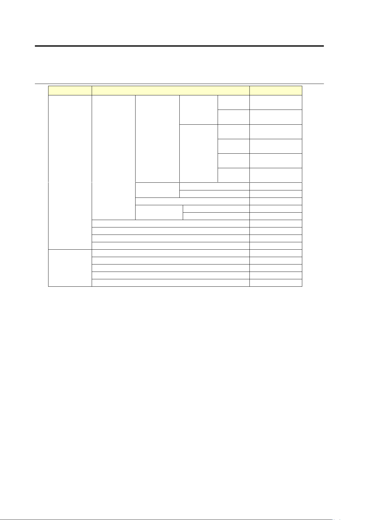
Window Type
Inspection Item
Optimization
Land Window
Fillet
Inspection
Wetting
Angle
Land
Wetting
Center of
Toe
●
Both Ends
of Toe
●
Component
Wetting
Center of
Toe
●
Both Ends
of Toe
●
Center of
Side
●
Both Ends
of Side
●
Fillet Height
Joint Height
●
Maximum Height
●
Fillet Length
●
Fillet Joint
Length
End Joint Width
●
Side Joint Length
●
Exposed Land
●
Land Error
×
Foreign Objects (Land)
○
Exposed Basis Metal (Oblique)
●
Inspection
Region
Window
Solder Ball
×
Solder Bridge
×
Foreign Material
×
Solder Ball (Oblique)
×
Solder Bridge (Oblique)
×
○:Optimization possible
●:Optimization possible (Optimization
taking the Boolean expressions
into consideration)
×:Optimization impossible