Omron V-TS Teaching Manual.pdf.pdf - 第111页
Chapter 2 Inspecti on Programm ing 2- 84 1. Select the [Criteria S etting (Product No.)] t ab to displa y the Criteria Setting screen. 2. Select the target com ponent in the Com ponent Num ber List. W hen the status is (…
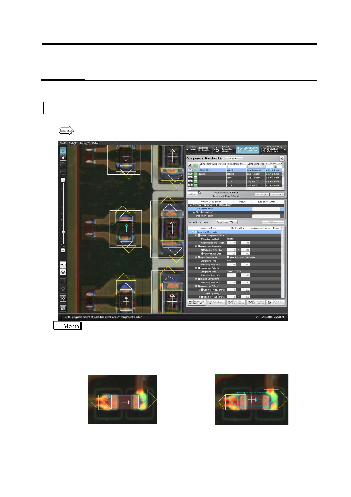
2.6 Specifying Inspection Criteria
2-83
2.6 Specifying Inspection Criteria
This section explains the procedure to specify inspection criteria for individual inspection
windows.
2.6.1 Criteria Setting (Product No.)
Specify inspection criteria for each component number.
Refer to "2.6.2 Criteria Setting (Individual Component)" for the criteria setting for individual
components.
On the Criteria Setting screen, the center position of the component is aligned to the reference
position for component offset inspection (the center of the minimum bounding rectangle for land
and electrode windows).
The component window must be aligned to the component image to teach the component colors
before registering the component number model. However, once the component number model
is registered, the alignment of the component window to the image is not required.
<Before Component Number Model Registration> <After Component Number Model Registration>
Chapter 2 Inspection Programming
2-84
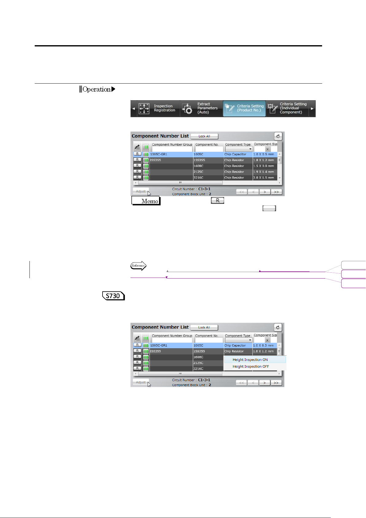
1.
Select the [Criteria Setting (Product No.)] tab to display the Criteria
Setting screen.
2.
Select the target component in the Component Number List.
When the status is (locked), click it to change the
component number status to not locked .
If you select a component number belonging to a component
number group, all the component numbers in the component
number group are included in the adjustment.
To automatically adjust individual inspection windows, select the
target component number in the component number list, and click
[Auto Adjustment].
Refer to (5) Information Display Area of "2.1.2 Configuration of the
Editing Screen".
<Setting ON/OFF height inspection based on the component
number>
By selecting and right-clicking a component number from the
component number list, height inspection can be set ON/OFF.
This function switches the inspection ON/OFF checkboxes of height
inspection of the selected component number in block.
For example, use this function when setting ON height inspection in
block for the inspection programs which were created in and before
version 1.55 which did not have any height inspection functions or
setting OFF height inspection in block due to the influence of
shadow.
Operation
変更されたフィールド コード
書式変更: フォント : Arial, 9 pt
削除: Configuration of the Editing Screen
2.6 Specifying Inspection Criteria
2-85
Height inspection means the following inspection logics:
■ Component inspection (wrong polarity, component height, and
lifted component)
■ Electrode inspection (electrode posture - lifted electrode /
coplanarity)
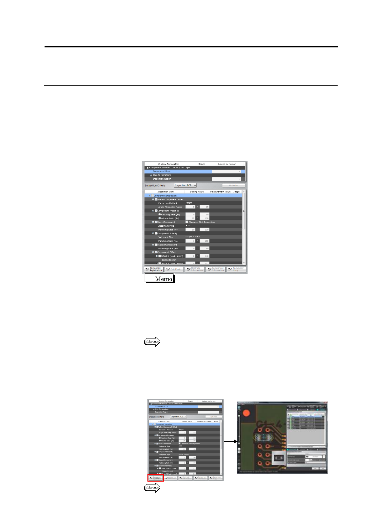
3.
Select the target window in the Window Composition, or click the
window in the image display area to select it.
The inspection items pertaining to the selected window are
displayed.
Use the combo box to switch the display of the
inspection PCB image and unpopulated PCB image.
4.
Select the inspection items by using the checkboxes.
Inspection is performed for the items whose checkboxes are ON,
and not performed for those with checkboxes OFF.
The inspection items with selected checkboxes require the
inspection criteria for a good component judgment.
Refer to the Inspection Logic Manual for the details on the
inspection items.
5.
To check or edit the component information, click to select the
Component Body item in the Window Composition, and click
[Component Registration].
The display moves to the Component Setting screen, where the
component information can be changed.
Refer to "2.4.5.1 Component Setting" for the editing procedure.