Omron V-TS Teaching Manual.pdf.pdf - 第318页
Appendix 9. Land Insp ection Adjustm ent Procedure a- 41 The f illet excluded color is not set appropriatel y . 1) Move to the “ Cr iteria Setting ” tab. 2) Select “ Inspection Criteria ” - “ Solder T op Center (Solder T…
Appendix 9. Land Inspection Adjustment Procedure
a-40
Appendix 9. Land Inspection Adjustment Procedure
This chapter hereafter describes causes of false call or overlooking and the procedure to confirm and
repair the fault when optimization is performed after the initial adjustment flow is executed and false call
or overlooking still remains on the wetting items of the land inspection.
For details of the wetting items of the land inspection, refer to P5-1 section 5. “Land
Inspection” of the inspection logic manual.
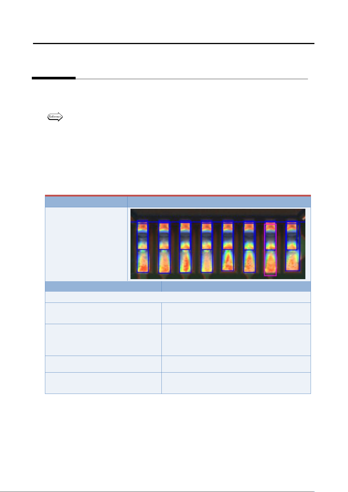
Inspection item 1. Fillet - Connection wetting angle (land wetting)
Based on the solder color detected in the land window, inspect if the land is wet with solder.
If false call or overlooking still remains in the inspection result, it is displayed as a wetting error (land
side).
The inspection result image, cause, and repair method of wetting error (land side) are as follows:
Inspection result
Image
Wetting error (land side)
Cause
Confirmation/repair method
When position does not match between the land and land window:
The land window is not positioned
appropriately.
Refer to Appendix 7.2.
The land window in the vicinity of the
applicable component is not positioned
appropriately.
Refer to Appendix 7.2.
The fiducial correction is not appropriate.
Refer to Appendix 7.1.
The position correction color is not
appropriate.
Refer to Appendix 7.2.
Appendix 9. Land Inspection Adjustment Procedure
a-41
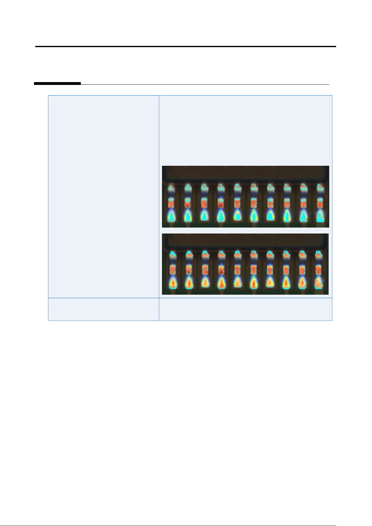
The fillet excluded color is not set
appropriately.
1) Move to the “Criteria Setting” tab.
2) Select “Inspection Criteria” - “Solder Top Center (Solder
Tip Both Ends)”, and click the [Model Editing] button.
3) Edit characteristic parameters using the color table editing
tool so that metal portion of the land (such as copper foil) is
extracted.
The inspection criteria are not set
appropriately.
Refer to Appendix 10.1.
Appendix 9. Land Inspection Adjustment Procedure
a-42
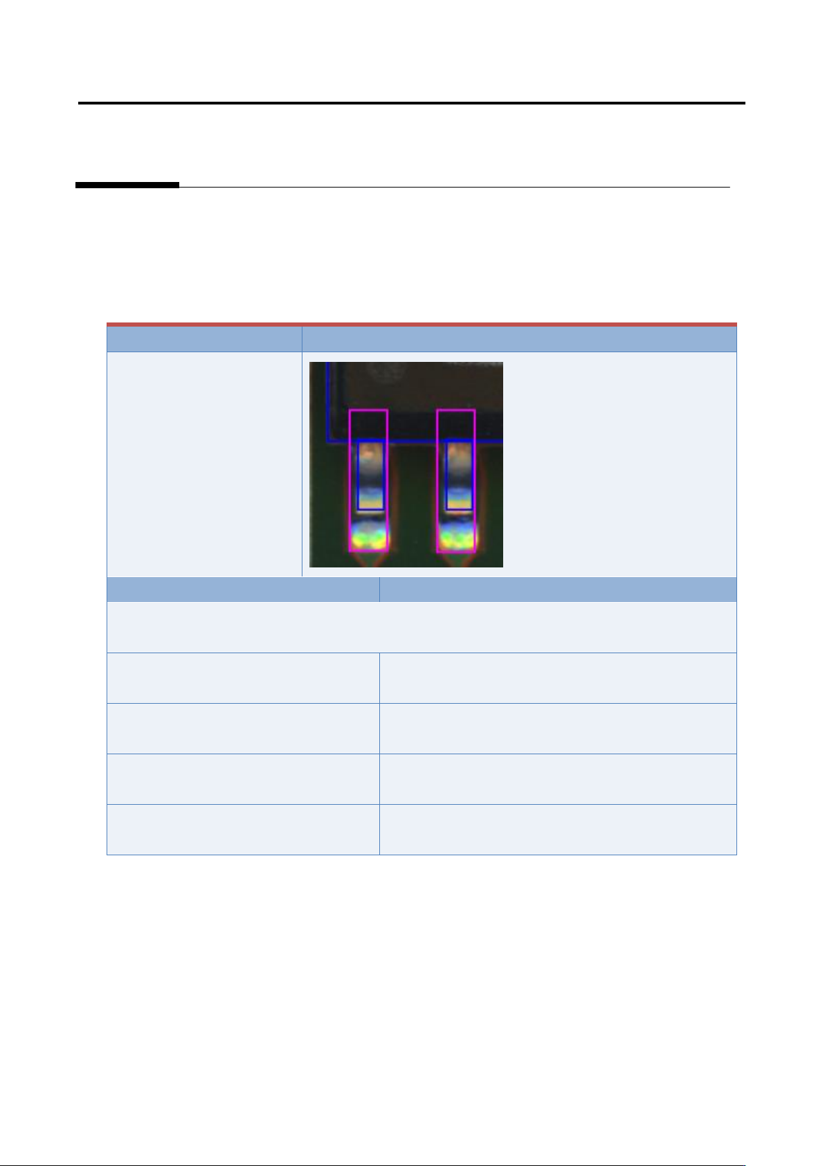
Inspection item 2. Fillet - Connection wetting angle (electrode wetting)
Based on the solder color detected in the land window, inspect if the electrode is wet with solder.
If false call or overlooking still remains in the inspection result, it is displayed as wetting error (electrode
end side).
The inspection result image, cause, and repair method of wetting error (electrode end side) are as
follows:
Inspection result
Image
Wetting error (electrode end
side)
Cause
Confirmation/repair method
When position does not match between the actual component (electrode) and extracted component
(electrode):
The component is not extracted in an
appropriate position.
Refer to Appendix 7.2.
The electrode tip is not extracted in an
appropriate position.
Refer to Appendix 7.7.
The electrode side is not extracted in an
appropriate position.
Refer to Appendix 7.6.
The electrode window is not sized
appropriately.
Refer to Appendix 7.5.