Omron V-TS Teaching Manual.pdf.pdf - 第289页
Appendix 5. Real Fault Re gi stration Pro cedure a- 12 ↓ Land Foreign object (Land) ↓ Wetting error
Appendix 5. Real Fault Registration Procedure
a-11
Appendix 5. Real Fault Registration Procedure
Register real fault using the procedure below.
1. Select the “Criteria Setting (Component Number)” tab.
2. Select a component number with which a visual inspection result is registered from the
component number list, and click [Model Editing].
3. Select a thumbnail image with which you wish to enter a visual inspection result from the
component thumbnail image list, and select a visual inspection result from the pull-down of
visual inspection results of window configuration. If more than one window is selected, the same
visual inspection result is registered in all the selected windows of the same type.
4. To go on to enter visual inspection results in the other thumbnail images, repeat step 3.
For details of real fault registration, refer to P2-162 Section 2.15.5 “Registering Visual Check
Results.”
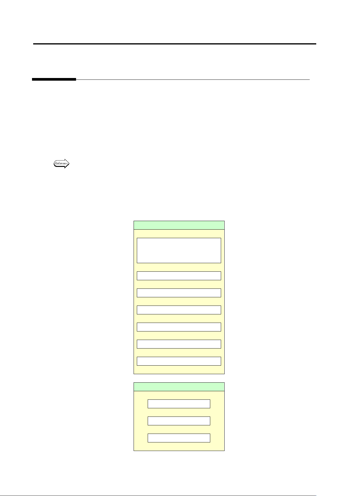
In optimization, fault detection is made in order of priority: (1) component, (2) electrode and (3) land. In
the case where both component and electrode are faulty, the system judges that the fault has been
detected as long as the component is judged as fault so that it does not detect the electrode fault. If the
electrode has been judged as fault, the visual inspection result is registered as the detected inspection
item name if there is no problem on the judgment.
Component
Missing component
* Including lifted component
and component breakage
↓
Component difference
↓
Polarity difference
↓
Upside down
↓
X position gap
↓
Y position gap
↓
Component skew
↓
Electrode
Side overhang
↓
End overhang
↓
End overlap
Appendix 5. Real Fault Registration Procedure
a-12
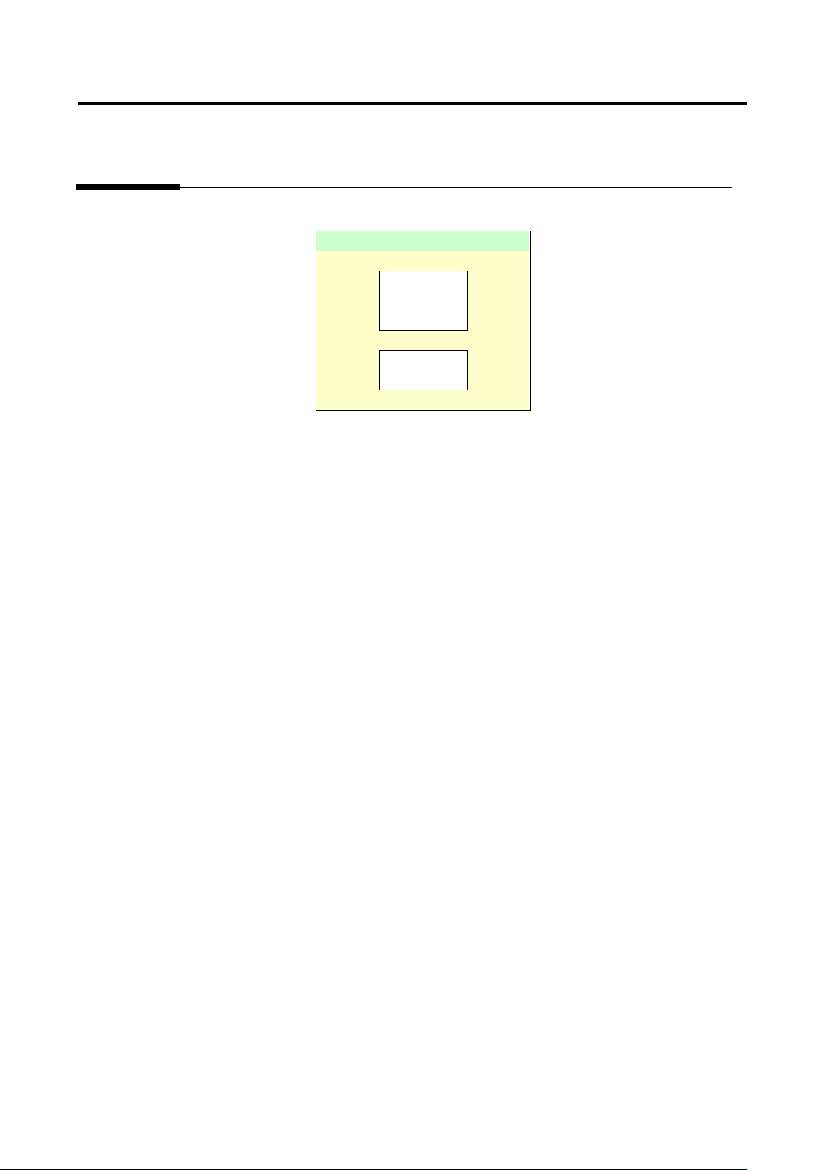
↓
Land
Foreign
object
(Land)
↓
Wetting
error
Appendix 6. Selection of Optimization Items
a-13
Appendix 6. Selection of Optimization Items
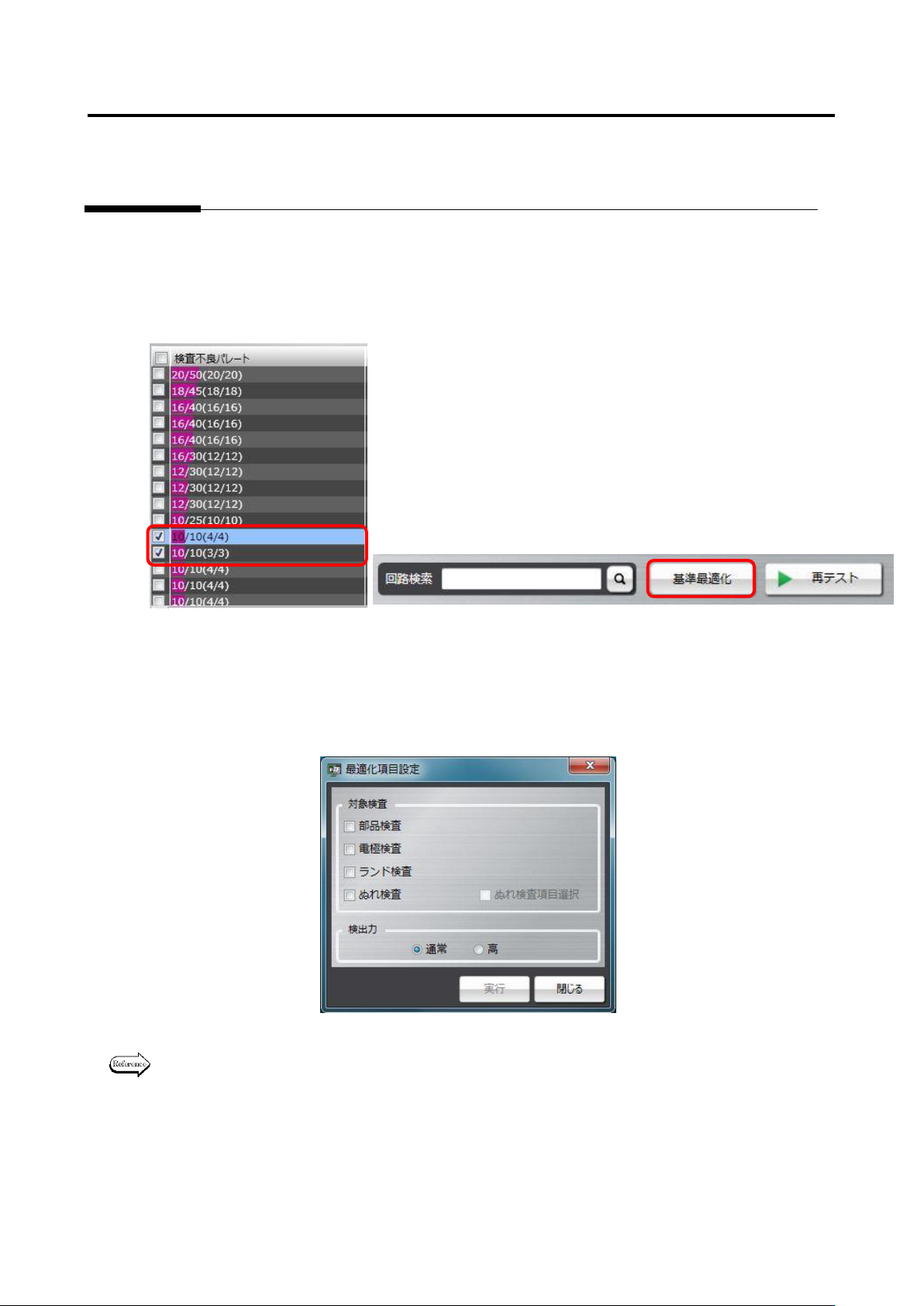
Optimization is a tool to automatically set a logical expression suitable for the component type and
electrode type of the component number when inspection criteria are set up.
To use optimization, select a component number or a component number group to be optimized on the
result confirmation screen as framed in red below, and press the Optimize Criteria button. Since
reference values are changed to suitable values, if there is a component number and so on you don’t
wish to change, perform optimization without selecting it.
Then, options can be selected for the target inspection and inspecting ability items.
When optimization is performed, selecting all options of the target inspection item is recommended.
However, if you don’t wish to change the criteria of the inspection program, select necessary inspection
options only, and perform optimization.
For details of the optimization execution method, refer to P2-154 Section 2.15.4 “Optimizing
Boolean Expressions and Inspection Criterion Values” of the Teaching Manual.