Omron V-TS Teaching Manual.pdf.pdf - 第160页
2.15 M odifying an Inspection Pr ogram 2- 133 2.15.2 Changing Comp onent and Electrode Inform ation This section explains the proce dure to change com ponent inform ation and electro de information. W hen you c hange the…
Chapter 2 Inspection Programming
2-132
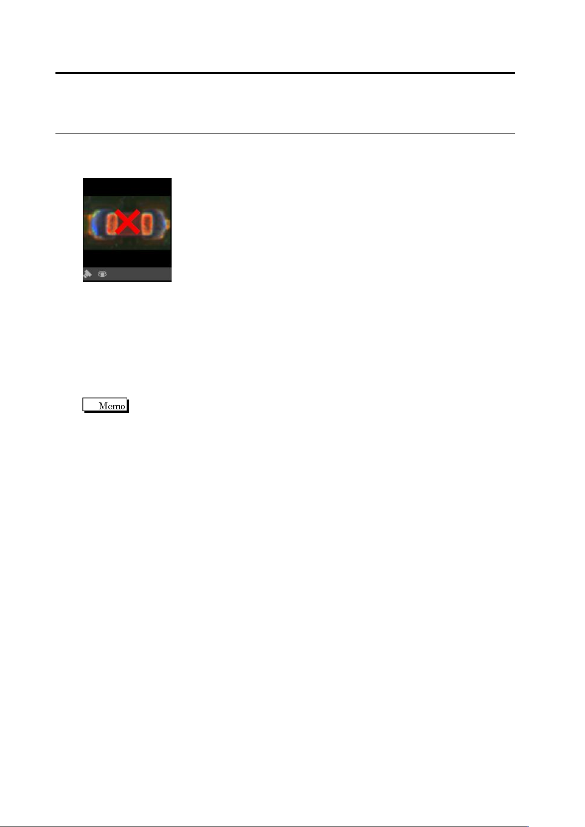
If the Component Window or Electrode Window protrudes from the model image after modifying
the Component Window size, [x] appears in the model image and the image becomes
unavailable.
When the Component Window/Electrode Window is moved back within the image, the model
image becomes available.
・ Automatic Window Position Adjustment
This function moves a Component/Electrode Window to an inspection standard position
calculated from an auto-extracted Land Window.
On the menu bar of the edit screen, select [Tool] - [Move a component to inspection standard
position].
The criteria of component offset are the window position on the inspection program screen. So,
if a component is changed or added after an inspection program is created completely, the
position of component window can be moved to the default position of the displacement
inspection criteria.
2.15 Modifying an Inspection Program
2-133
2.15.2 Changing Component and Electrode Information
This section explains the procedure to change component information and electrode information.
When you change the information on component or electrode, these changes will be reflected to
all the components of the same component number or component number group within the
inspection program.
When you make a change such as changing the angle or electrode group that affects the model,
adjust the component color and electrode color on model editing.
The Criteria Setting (Product No.) screen also can be used to only change the electrode height.
Refer to Step 5 on “2.6.1 Criteria Setting (Product No.)” for the procedure to change electrode
height.
The Criteria Setting (Product No.) screen also can be used to only change the component height.
Refer to Step 5 on “2.6.1 Criteria Setting (Product No.)" for the procedure to change component
height.
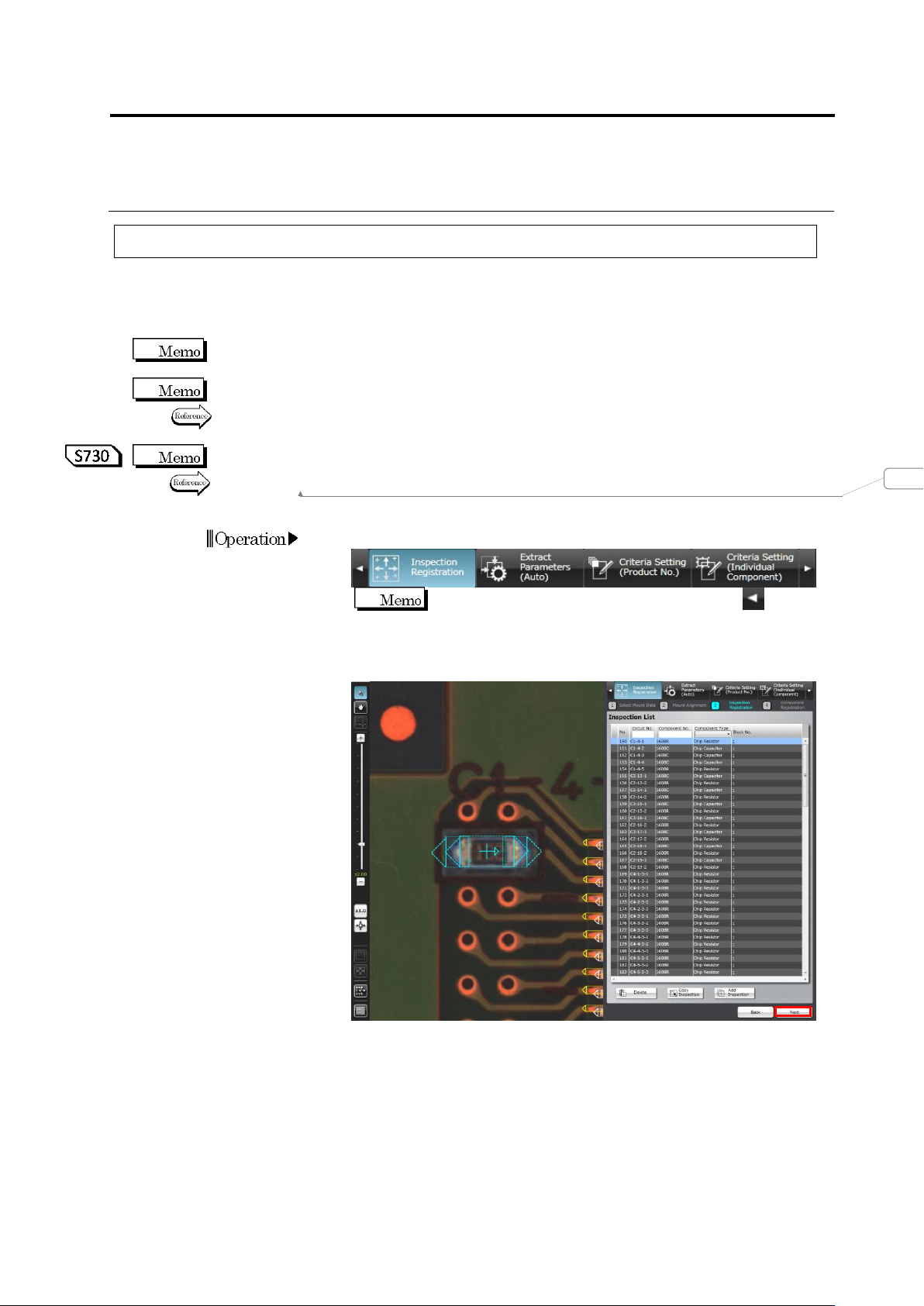
1.
Select the [Inspection Registration] tab.
If the [Inspection Registration] tab is hidden, click at the
left to display it.
2.
The display moves to the Inspection Registration screen. Click
[Next].
変更されたフィールド コード
Chapter 2 Inspection Programming
2-134
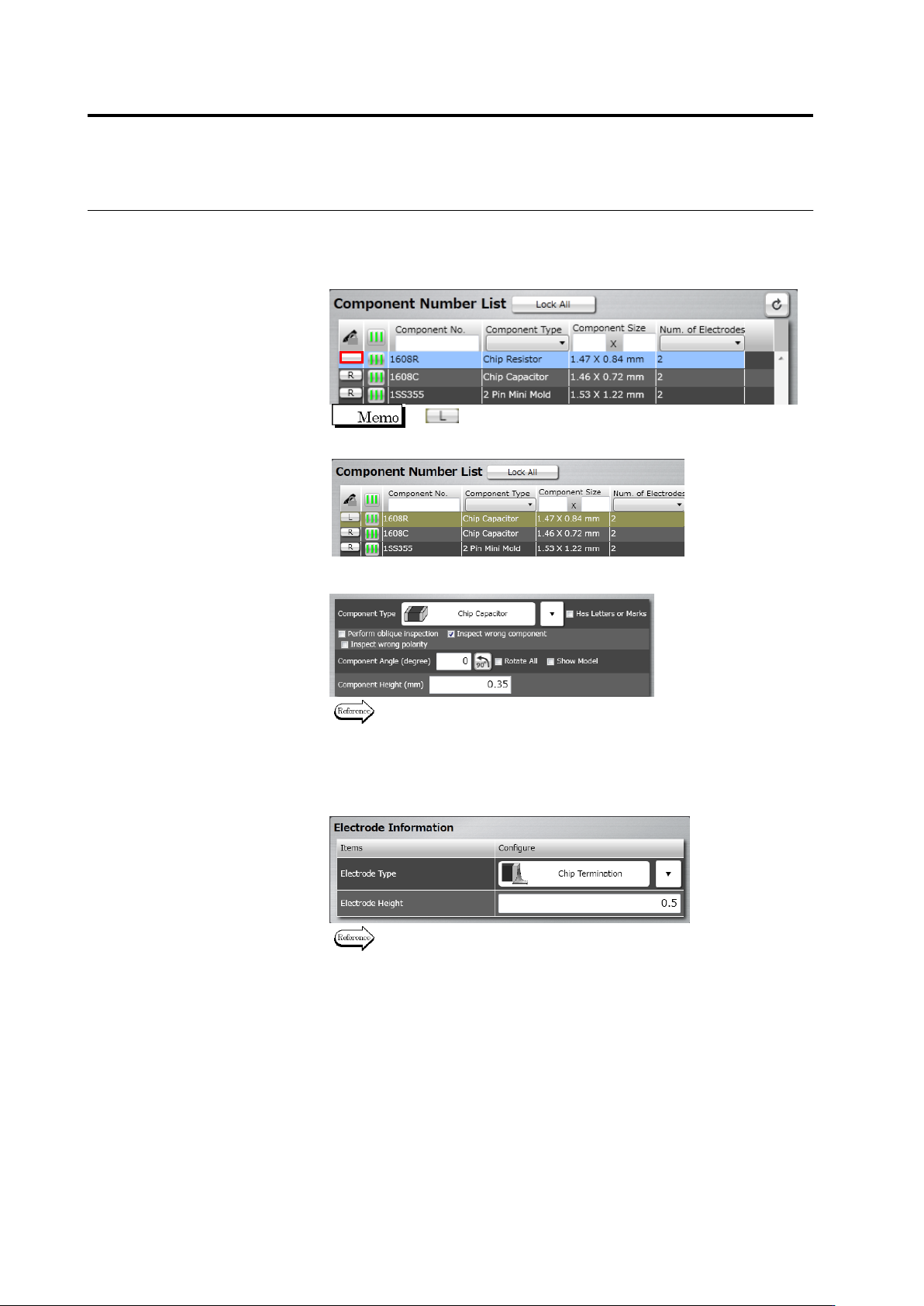
3.
The Component Registration screen is displayed.
Click the [R] (Read-only) button for the target component number to
cancel the Read-Only mode. “R” disappears when canceling
Read-Only mode.
If (Locked) is displayed, editing is not possible since
other user is currently editing the component number.
4.
Edit the component information.
Refer to "2.4.5.1 Component Setting" for the editing procedure.
5.
Click [Next] several times until the Electrode Setting screen
appears.
6.
Specify electrode information for individual electrode groups.
Refer to "2.4.5.4 Electrode Setting" for the electrode setting
procedure.
7.
Click [Component Number Registration] after all the groups are
specified with the electrode information.