Omron V-TS Teaching Manual.pdf.pdf - 第59页
Chapter 2 Inspecti on Programm ing 2- 32 4. The following dialog ap pears. Capture the bare board and g ood inspection PCB im ages with the PC B inspection s ystem . Refer to the Operation Manual of the inspection machin…
2.2 Creating a New Inspection Program
2-31
書式変更: フォント : (日) MS ゴシッ
ク, 10 pt
削除: Creating a New Inspection Progra
m
■ Inspection Surface
Select the inspection PCB surface.
■ Land height offset (mm)
Enter the height difference between the land and wiring pattern.
The reference surface is generated using the wiring
pattern height. So, register an offset value to set the land surface
height to zero.
■ Adjust Land Size Individually
Select the checkbox to enable the auto adjustment of the land
windows individually when windows are positioned to multiple
components of the same component number for component
registration.
If the checkbox is not selected, the land windows of the same size
as those positioned on the sample component are placed on all
the components with the same component number.
The checkbox is selected by default.
Deselect the checkbox if the land color teaching is difficult as
in e.g. solder leveled PCB teaching.
■ Quality Criteria
Select the criteria rule book to use in the pull-down menu.
By default, one of the following two can be selected:
・Default Level1-Ver200E: Preference for direct pass rate
・Default Level2-Ver200E: Preference for fault detection
Refer to P3-4 "3.3 Configuring Quality Criteria Setting" for the details
and editing method on criteria rule books.
■ Comment
Enter comments such as supplemental information regarding the
inspection program within 256 characters. (This is not
case-sensitive.)
Alphanumerical characters and symbols can be used.
Chapter 2 Inspection Programming
2-32
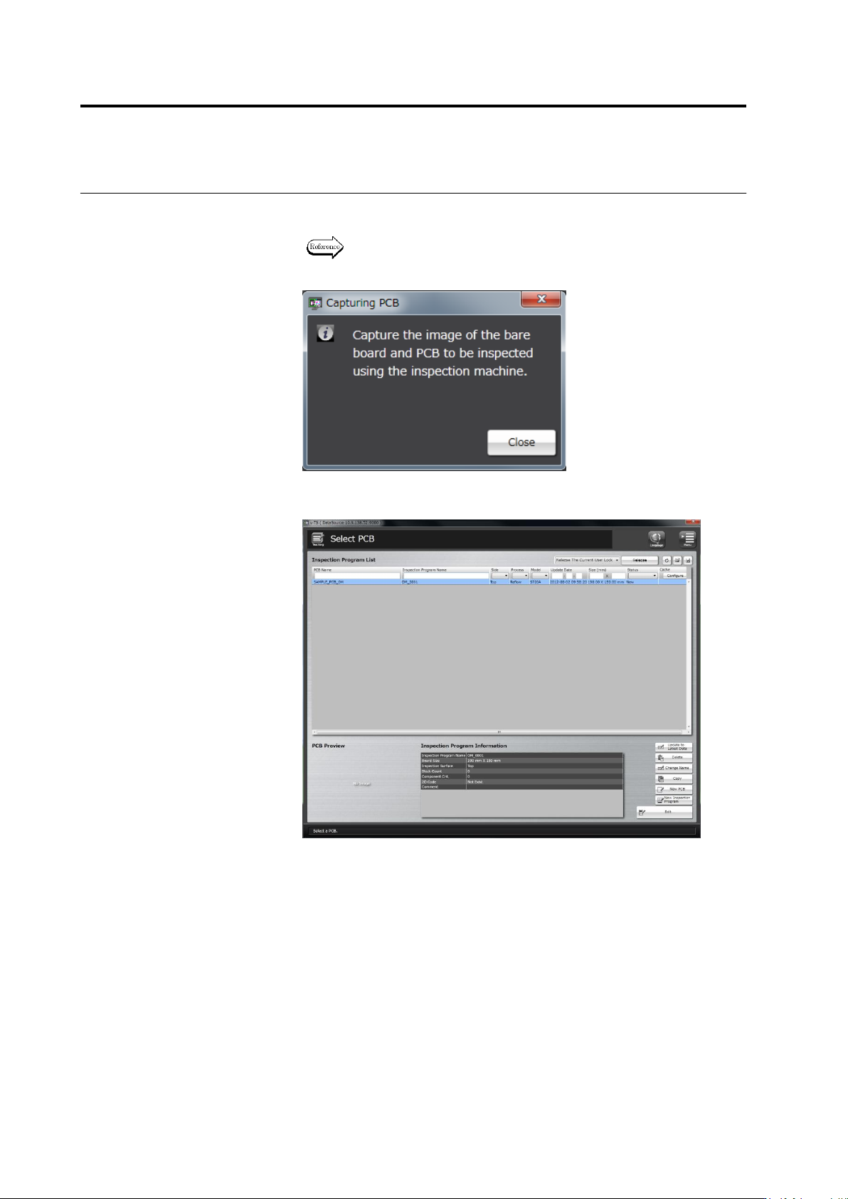
4.
The following dialog appears. Capture the bare board and good
inspection PCB images with the PCB inspection system.
Refer to the Operation Manual of the inspection machine, Chapter 3:
“Capturing PCB Image" for the procedure to capture a PCB image.
Click [Close]. The dialog closes and the Select PCB screen returns.
2.3 Opening an Inspection Program
2-33
2.3 Opening an Inspection Program
This section explains the procedure to open an inspection program.
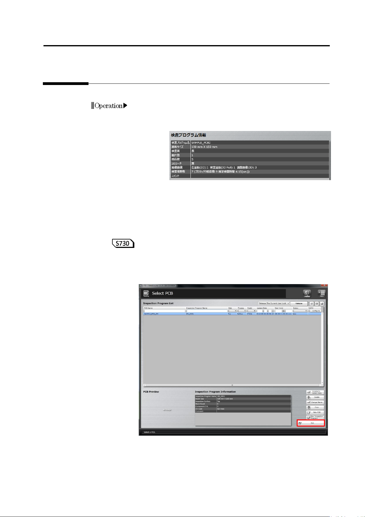
1.
Select a desired inspection program in the Inspection Program List
in the Select PCB screen.
When an inspection program is selected, information on the
inspection program is displayed.
The content of the inspection program is as follows:
■ Information on the PCB and inspection program is displayed.
Inspection program name, PCB size, inspection side, and
comment
■ Details of the inspection program is displayed.
Number of component block units, number of components,
presence/absence of 2D code, types and numbers of captured
images, number of inspection fields of view including direct view
and oblique view
Number of projections from projectors and estimated inspection
time (sec.)
2.
Click [Edit] to open the program.
The following message appears if the PCB image is not captured yet.
Capture the bare and inspection PCB images with the PCB
inspection system and click [Edit] again.
Operation