Omron V-TS Teaching Manual.pdf.pdf - 第96页
2.4 Registeri ng f or Insp ection 2- 69 To change the group set ting, double- click the Electrode Gr oup cell in the Electrode Group L ist to select the group. If the number of groups is not suff icient, click [Add Group…
Chapter 2 Inspection Programming
2-68
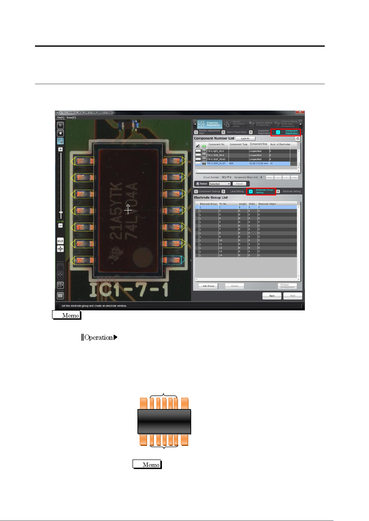
2.4.5.3 Electrode Group Setting
This section describes the creation of electrode windows and setting of electrode groups.
Drawing windows is not required for chip-type components (i.e. chip resistors, chip capacitors
or other chip components), since the electrode windows are automatically extracted.
1.
Set groups for each electrode.
Divide electrodes of different shapes and sizes into separate groups,
since the electrode inspection criteria are specified by the unit of
group.
The example below shows the group setting for an SOP with the
electrodes on both ends (specified as Group 2) larger than the
others.
The electrode group default setting is provided depending on
the land window size.
(2)
(2)
(2)
(2)
(1)
(1)
Operation
2.4 Registering for Inspection
2-69
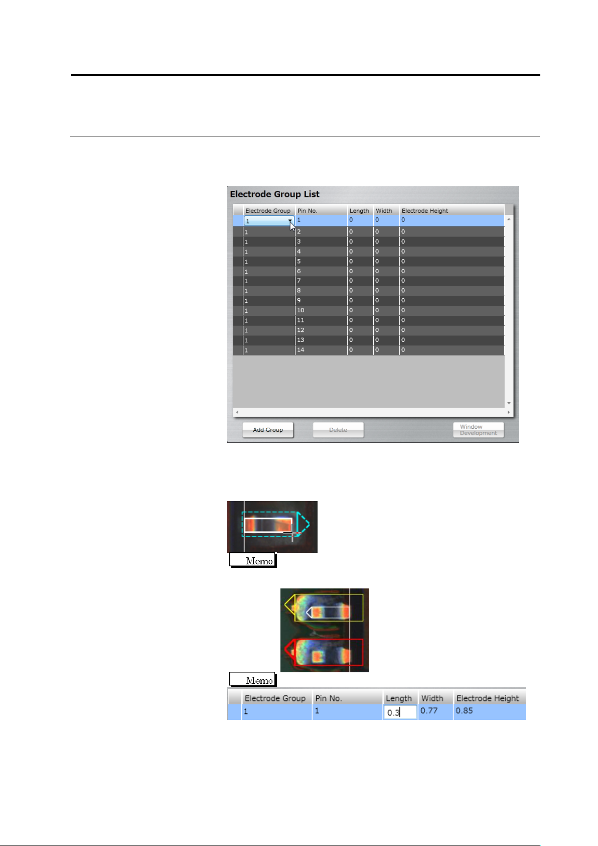
To change the group setting, double-click the Electrode Group cell in
the Electrode Group List to select the group.
If the number of groups is not sufficient, click [Add Group]. A new
group is specified under a new number.
2.
From the electrode group list, select a pin number to draw a
window.
The land window in the image display area is selected, a new
window is drawn to the electrode corresponding to its land window.
When you paste an electrode window to a land window that is
different from the land window being selected, the land window
becomes red and the [Next] button is disabled.
On the electrode row, you can enter an electrode size.
Chapter 2 Inspection Programming
2-70
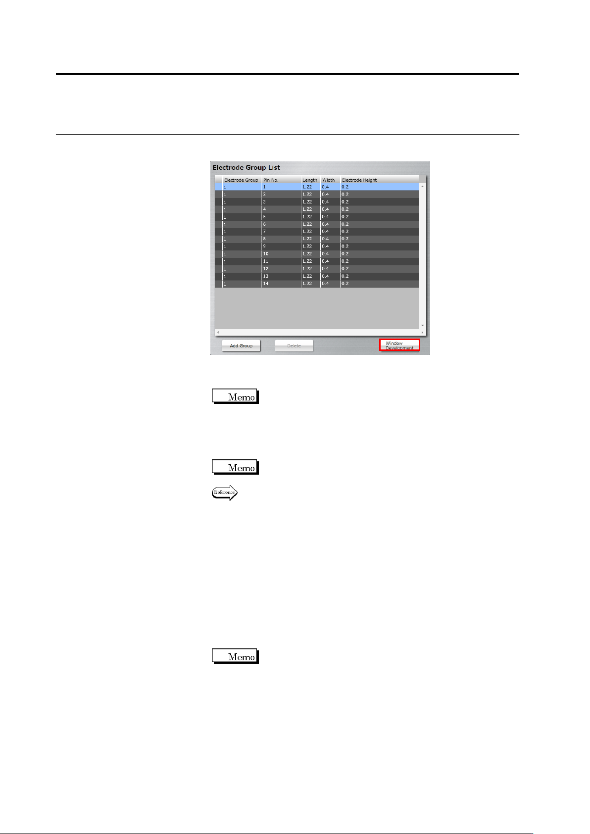
3.
Select the electrode window drawn in Step 2, click [Window
Development].
Windows of the same size as the selected electrode window are
positioned on the electrodes in the same group.
When the positions of the land window and electrode window
are not correct (land window is in red), the [Window
Development] button is disabled.
4.
Select an individual electrode window to adjust the position and
size.
When an electrode window is resized, other electrode windows
in the same group are also resized.
Refer to "2.1.3 Image Display Area Operation" for the image
display area operation.
5.
Perform Step 2 to 4 for each electrode group.
6.
When modifying the land window after setting the electrode window,
click [Back] to return to the land settings screen, modify the land
window and then click [Next]. When mismatch between the
electrode window and land window occurs (deleting a land, etc.),
the [Delete] button is enabled. When you click [Delete], all the
electrode windows are deleted. Perform operation from Step 1
again.
7.
Click [Next] to proceed to the Electrode Setting screen.
The [Next] button will be enabled when you set electrode
windows to all the land windows.