Omron V-TS Teaching Manual.pdf.pdf - 第262页
3.3 Configuring Qu ality Criteria Setting 3-7 3.3.3 Configuring El ectrode Type Inspe ction Criteria Initial settin gs of inspectio n criteria are done for each ele ctrode type in this sect i on. Setup det ails are manag…
3.3 Configuring Quality Criteria Setting
3-7
3.3.3 Configuring Electrode Type Inspection Criteria
Initial settings of inspection criteria are done for each electrode type in this section.
Setup details are managed in a sheet. If an electrode type is defined in more than one sheet,
the criteria in a sheet with higher priority are used for the initial setting.
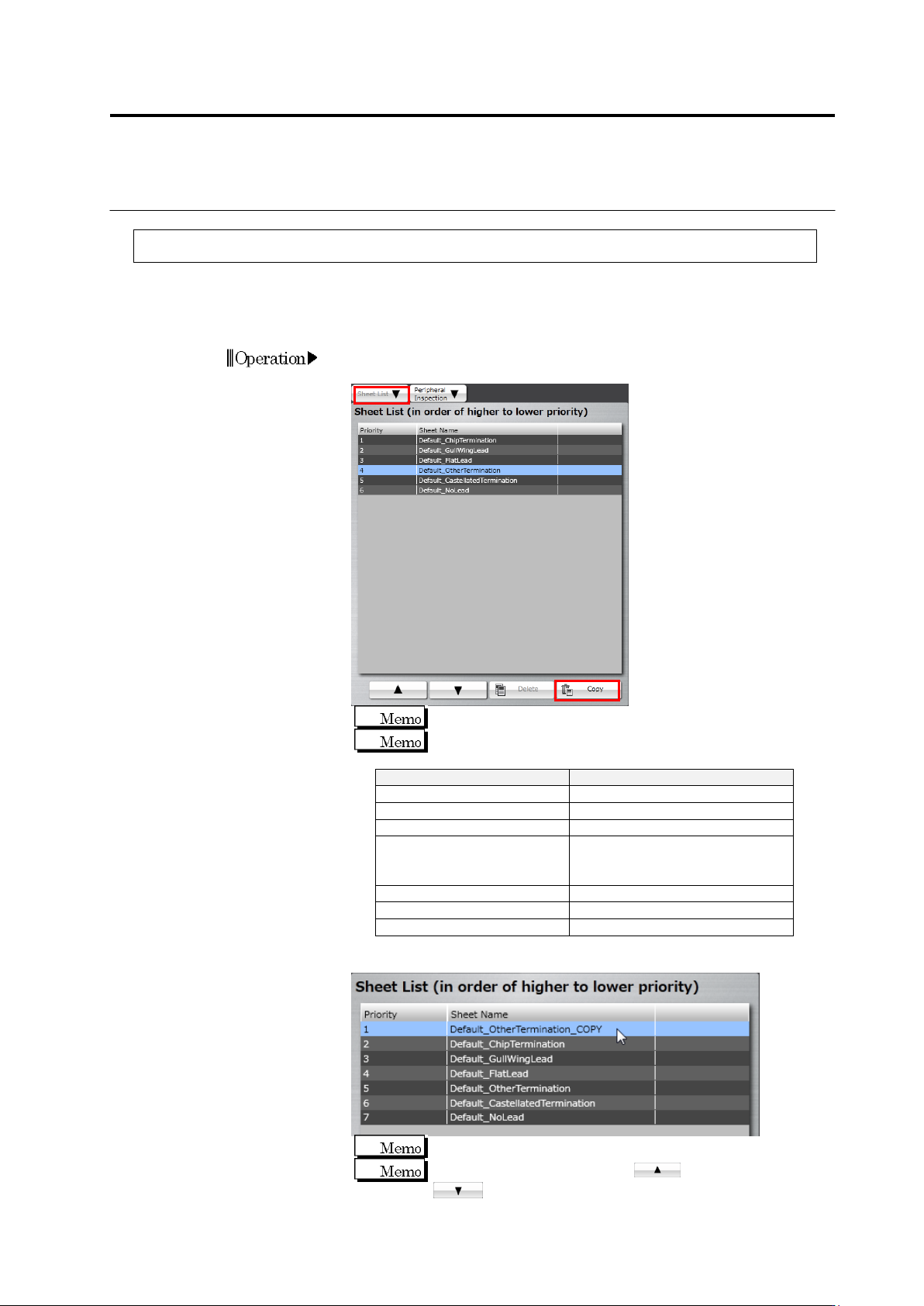
1.
Click the [Sheet List] tab, select a sheet of an electrode type you
want to edit from the sheet list, and click [Copy].
The default sheet cannot be edited.
Shown below are electrode types and the corresponding
sheets.
Electrode Type
Sheet Name
Chip Electrode
Default_ChipTermination
Gull-Wing Lead
Default_GullWingLead
Flat Lead
Default_FlatLead
Other Electrode
(Inward L-Shaped Lead, J-
Shaped Lead, Micro Lead)
Default_OtherTermination
Castellation Electrode
Default_CastellatedTermination
No Lead
Default_NoLead
Insertion Lead
Default_InsertionLead
2.
Click the sheet copied from the sheet list to select.
The copied sheet is displayed as priority 1.
To increase the priority, click . To decrease, click
.
Chapter 3 Management Menu
3-8
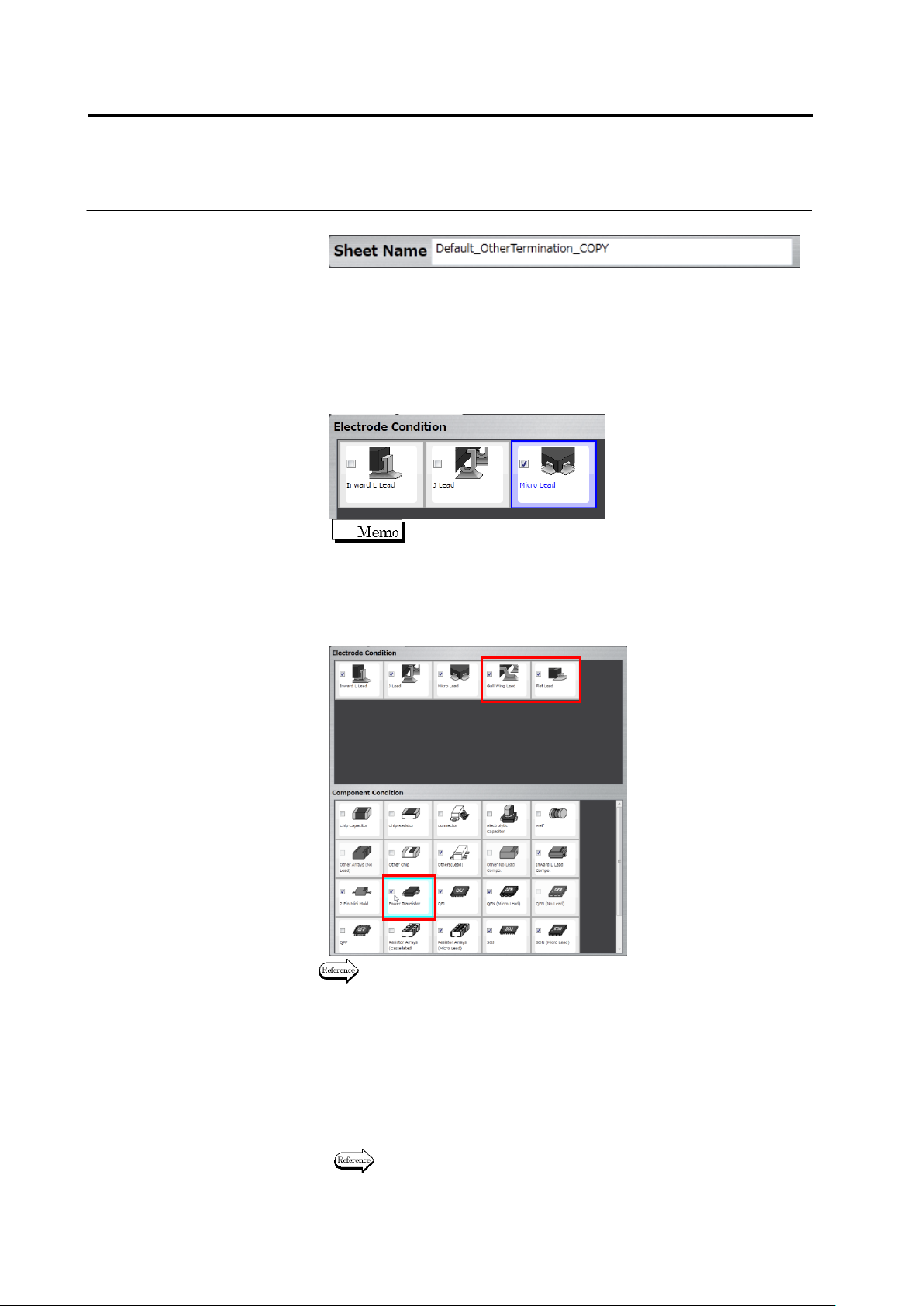
3.
Click the text box of [Sheet Name] to edit the sheet name.
4.
If an electrode condition is not displayed, click the [Electrode
Condition] tab.
5.
Set an electrode type for which you want to enable the inspection
criteria of this sheet.
Click a check box for each electrode type in the electrode condition.
Select the box to enable, or unselect it to disable.
On the component conditions, the check box is displayed as
being selected for a component type corresponding to the
enabled electrode type.
To add other electrode type than those displayed, select the check
box of a component type corresponding to the electrode type in the
component conditions.
For component types and the corresponding electrode types, see P2-7
“Component Types” and P2-8 “Electrode Types.”
6.
Click the [Inspection Criteria] tab to display the inspection criteria.
7.
Edit the initial setting of the inspection criteria.
If the check box is being selected, inspection for the item will be
performed. If not, it will not be performed.
For an inspection item with its check box being selected, set a
reference value for OK judgment.
For details of inspection items, refer to the inspection logic manual.
Add