Omron V-TS Teaching Manual.pdf.pdf - 第189页
Chapter 2 Insp ection Progr amming 2- 162 <Orthographic View > If height m easurement data is used for ins pection, orthographic view ap pears. Move the line profile to a location you want t o check, and verif y a …
2.15 Modifying an Inspection Program
2-161
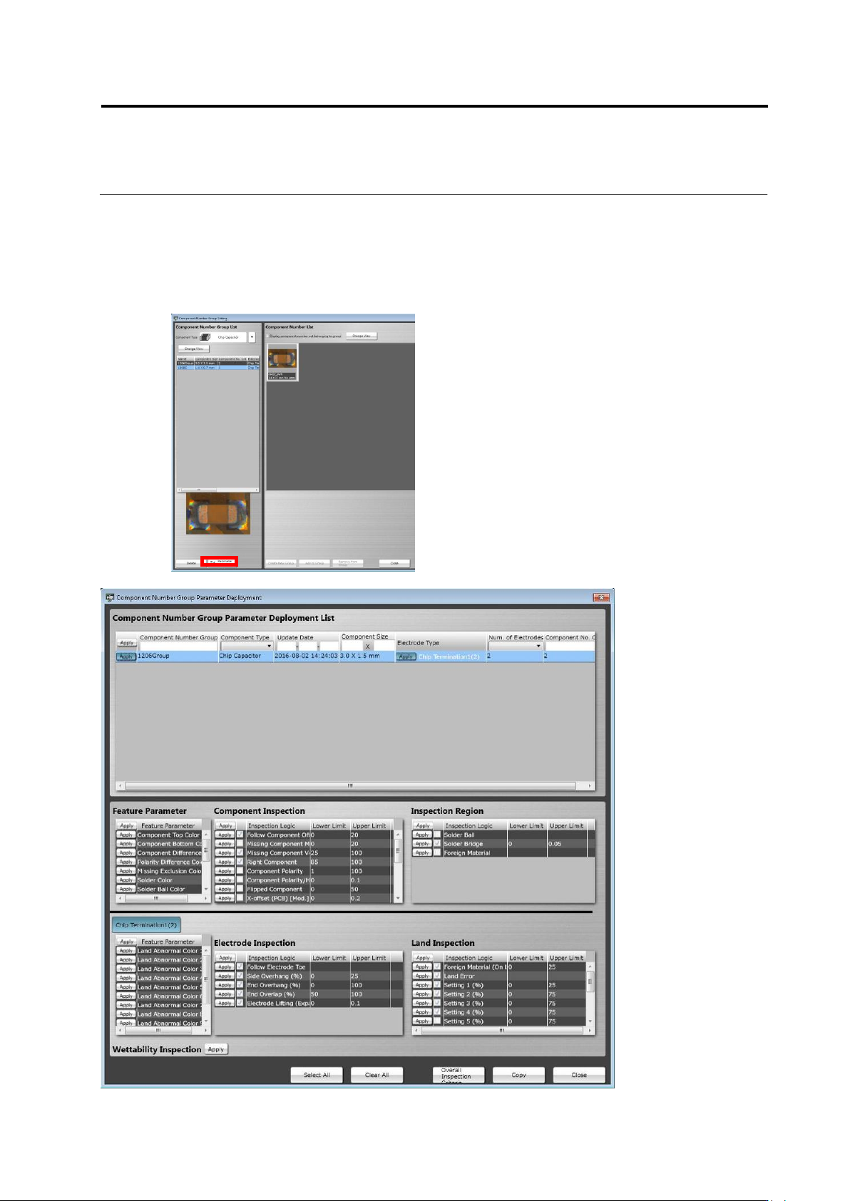
<Component Number Group Settings Deployment Tool>
The characteristic parameters and inspection criteria of the selected component number group
can be deployed to another component number.
On the component number group settings screen, click the [Deploy] button to open the
[Component Number Group Parameter Deployment] screen. The operation method of the screen
is equal to that of the component number settings deployment tool.
Chapter 2 Inspection Programming
2-162
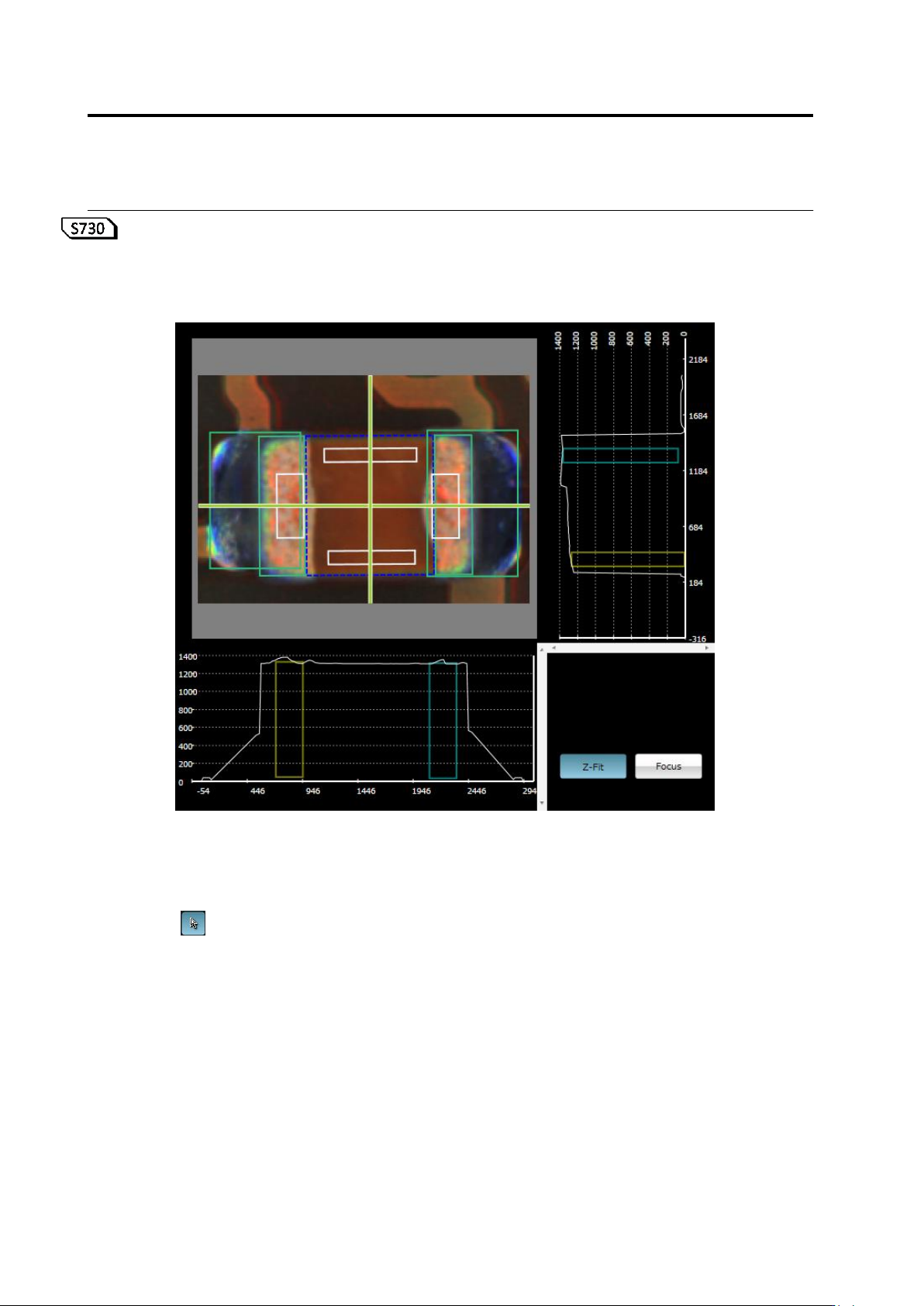
<Orthographic View>
If height measurement data is used for inspection, orthographic view appears.
Move the line profile to a location you want to check, and verify a component, component height,
and a fillet shape.
(1) X-Y Diagram
Displays a component thumbnail image.
(2) Line Profile Position Specification Line
Shows a slice position to display on X-Z and Y-Z diagrams.
If is set ON, you can move this by mouse dragging, cursor keys on the keyboard, or
left-clicking on the X-Y diagram while holding an Alt key.
The view is refreshed following the X-Y diagram view position and scaling.
⑤
⑥
(1)
(2)
(4)
(7)
(3)
(5)
(6)
2.15 Modifying an Inspection Program
2-163
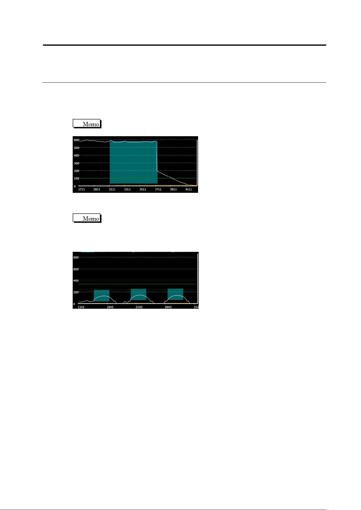
(3) X-Z Diagram
Displays the following slice information of X-Z.
Slice Height: White line
Electrode Position/Height: Light blue paint-out frame (displayed when fillet inspection,
electrode lifting, or coplanarity is selected)
If fillet inspection is selected, the electrode being selected is displayed as a light
blue paint-out frame.
Lifted Component Inspection Criteria: Green line (displayed when component lifting
or coplanarity is selected)
If coplanarity is selected, all the electrodes belonging to the electrode group
being selected are displayed as light blue paint-out frame. A green line is displayed at the
height of the lowest electrode, and the other green line is displayed at the height which is the
height of the inspection criterion above the former green line. The range of OK products for
coplanarity inspection is between these two lines.
(4) Y-Z Diagram
Displays the slice information of Y-Z. The details are the same as that of X-Z diagram.
(5) Z Scale Adjustment Toggle Button
Setting the button ON scales the Z axis so as to fit in the screen.
Setting the button OFF displays the Z axis in the same scale as X and Y.
(6) Window Centering Button
Clicking the button adjust the position of the selected window to the center of the X-Y
screen.