Omron V-TS Teaching Manual.pdf.pdf - 第89页
Chapter 2 Inspecti on Programm ing 2- 62 Follow the procedures b elow as required if the land window auto extrac tion failed. ・ A d d a Land Windo w Form a land window b y directly drawing it o n the image dis p lay area…
2.4 Registering for Inspection
2-61
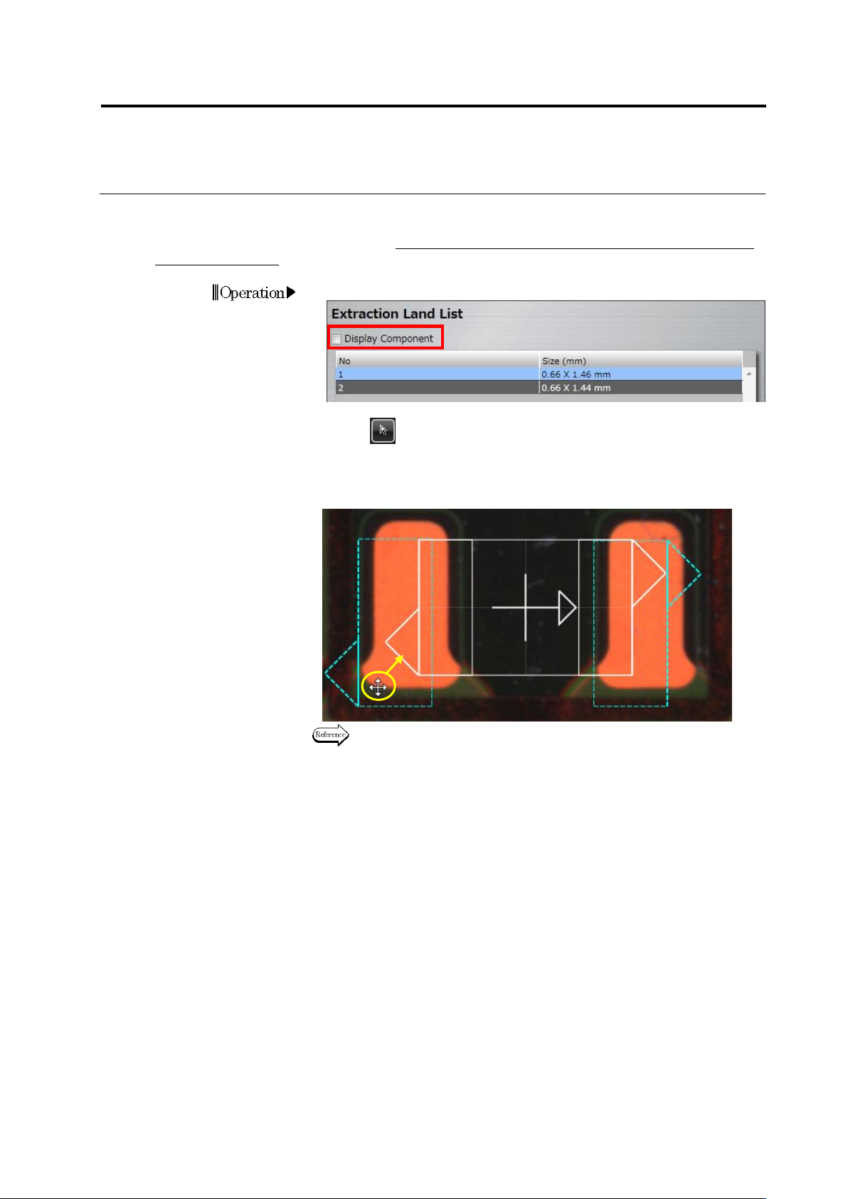
・ Adjust the Land Position
Align the auto-extracted land windows to the corresponding positions on the bare PCB image.
This operation is not usually required. Perform it only when the PCB is a leveler board or a raw
PCB is unavailable.
1.
Deselect the [Display Component] checkbox.
2.
Select (Select Window) in the Image Operation tool bar, if it is not
selected.
3.
Drag the land windows to the land positions on the bare PCB image
(area colored in orange on the image below).
Refer to "2.1.3 Image Display Area Operation" for the image display
area operation.
4.
Click [Next] to proceed to the Electrode Group Setting screen.
Operation
Drag
Chapter 2 Inspection Programming
2-62
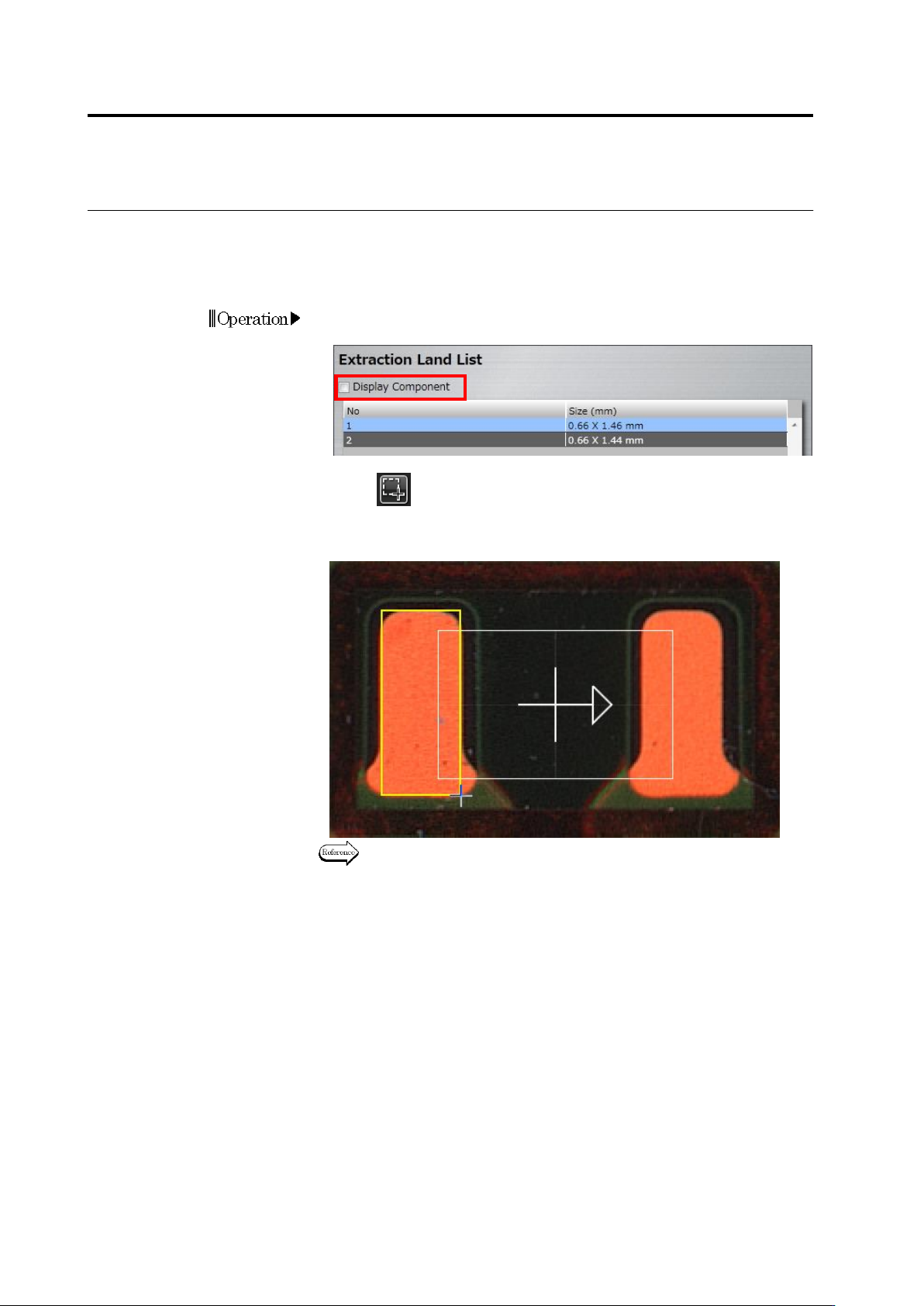
Follow the procedures below as required if the land window auto extraction failed.
・ Add a Land Window
Form a land window by directly drawing it on the image display area.
1.
Deselect the [Display Component] checkbox to display the bare
PCB image.
2.
Click (Create Window) button in the Image Operation tool
bar.
3.
Create a window by almost tracing the land shape on the image.
Refer to "2.1.3 Image Display Area Operation" for the image display
area operation.
Operation
2.4 Registering for Inspection
2-63
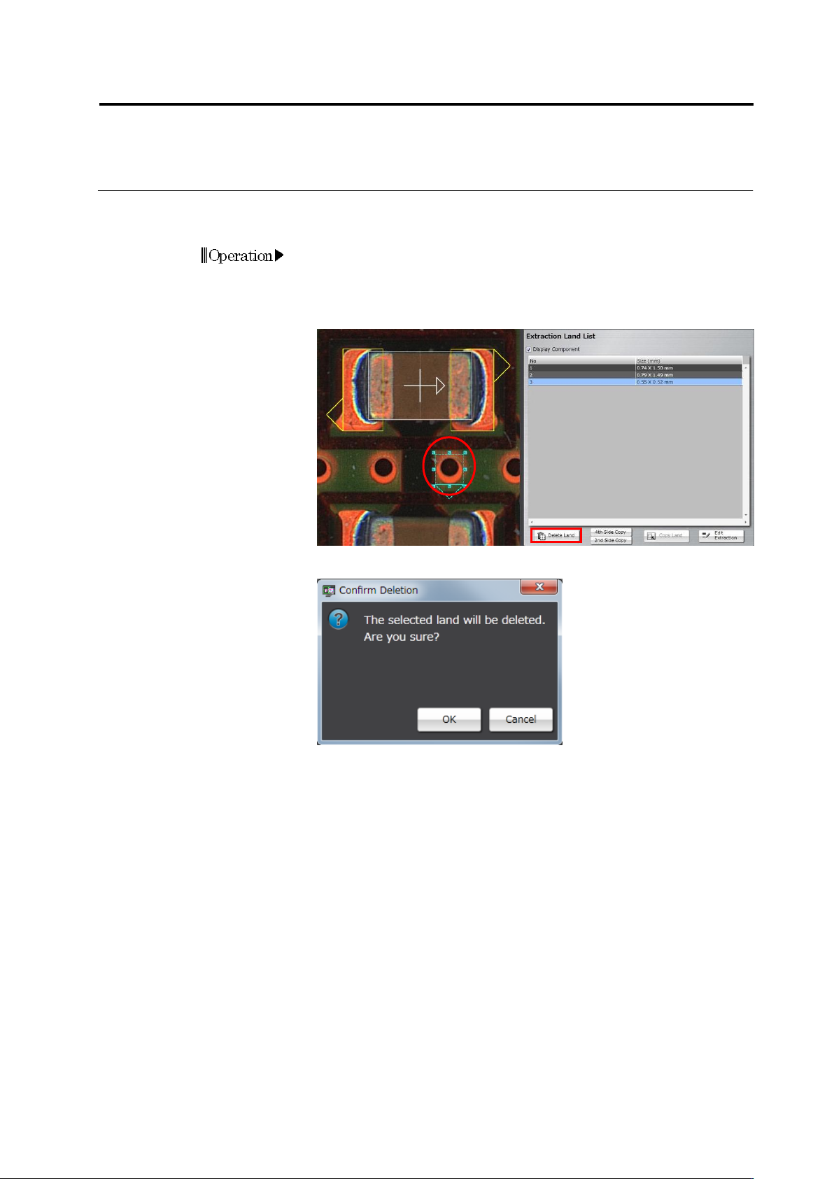
・ Delete a Land Window
Delete extra land windows automatically extracted, if there are any.
1.
Select the land to delete.
Click the land window in the image display area, or click the land in
the Extraction Land List.
2.
Click [Delete Land].
3.
The following dialog appears. Click [OK].
Operation