Omron V-TS Teaching Manual.pdf.pdf - 第227页
Chapter 2 Insp ection Progr amming 2- 200 Hereafter the eff ect of this function is sho wn. Before setup After setup <Base plane m anual partitioning f unction> This function can gener ate m ore than one base plane…
2.16 Managing PCB Images
2-199
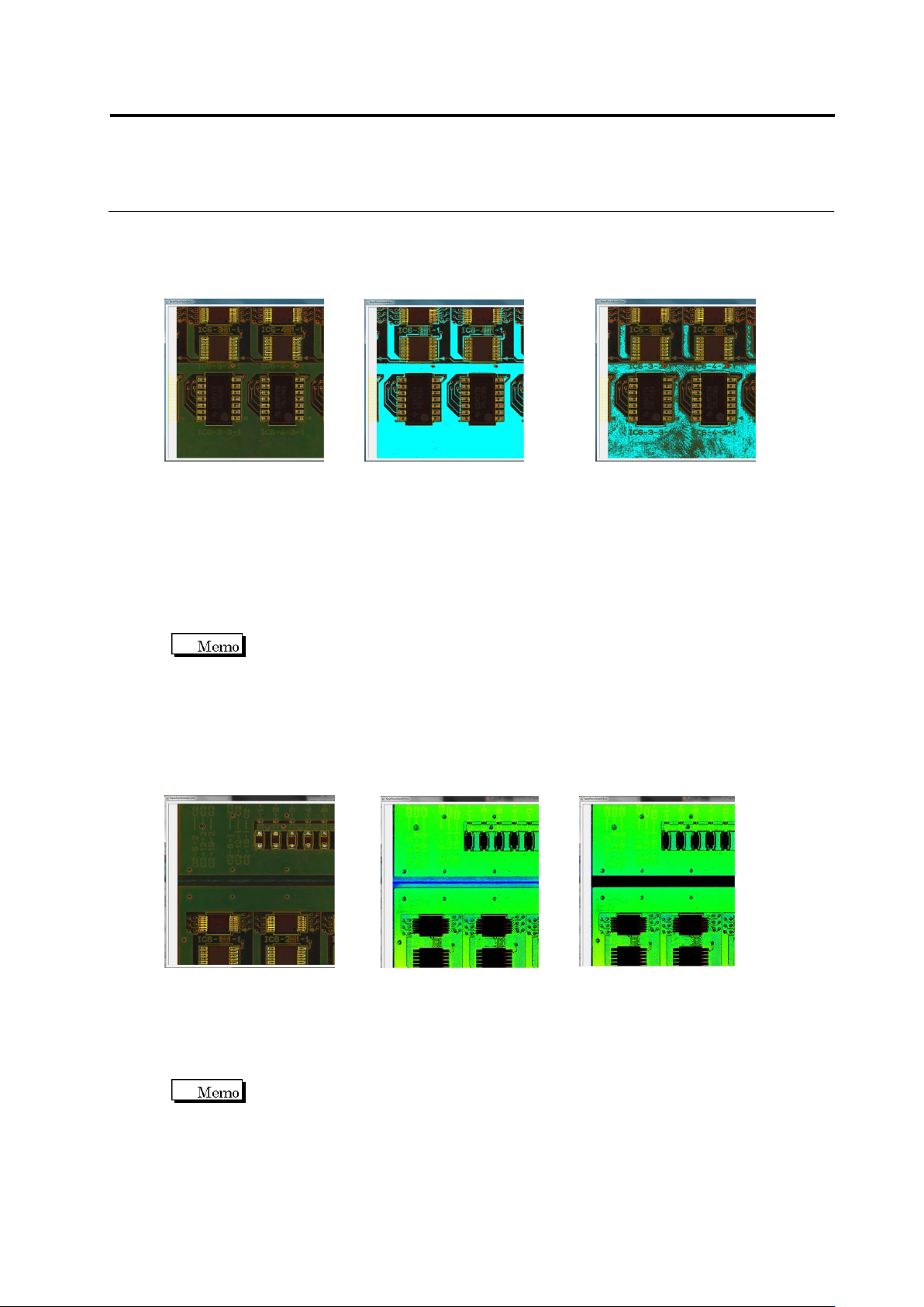
Hereafter, good and bad examples of base plane binarization are described.
RGB image Good example Bad example
(Base plane is binarized) (Base plane is not binarized)
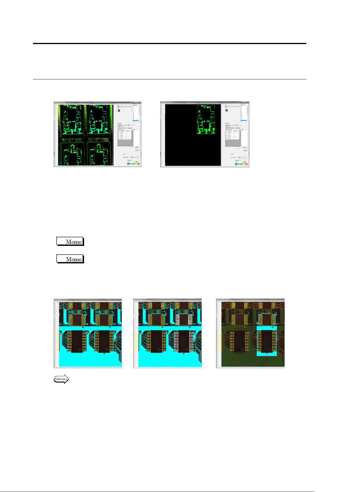
<Confirmation of base plane height image and mask adding function>
If the base plane of the overall FOV is not displayed in green, add a mask using the ④ Add
mask button to set the base plane correctly.
To add a mask, click the ④ Add mask button and drag an area to be masked. The added mask
is displayed on the ⑱ mask list of the selected inspection FOV.
To delete a mask, select the mask on the ⑱ list and click the [Delete] button. To
delete all the masks, press the ⑳ [Delete All Masks] button.
Hereafter, a base plane height image before and after adding a mask is shown.
RGB image Before adding mask After adding mask
(Noise occurs) (Noise eliminated)
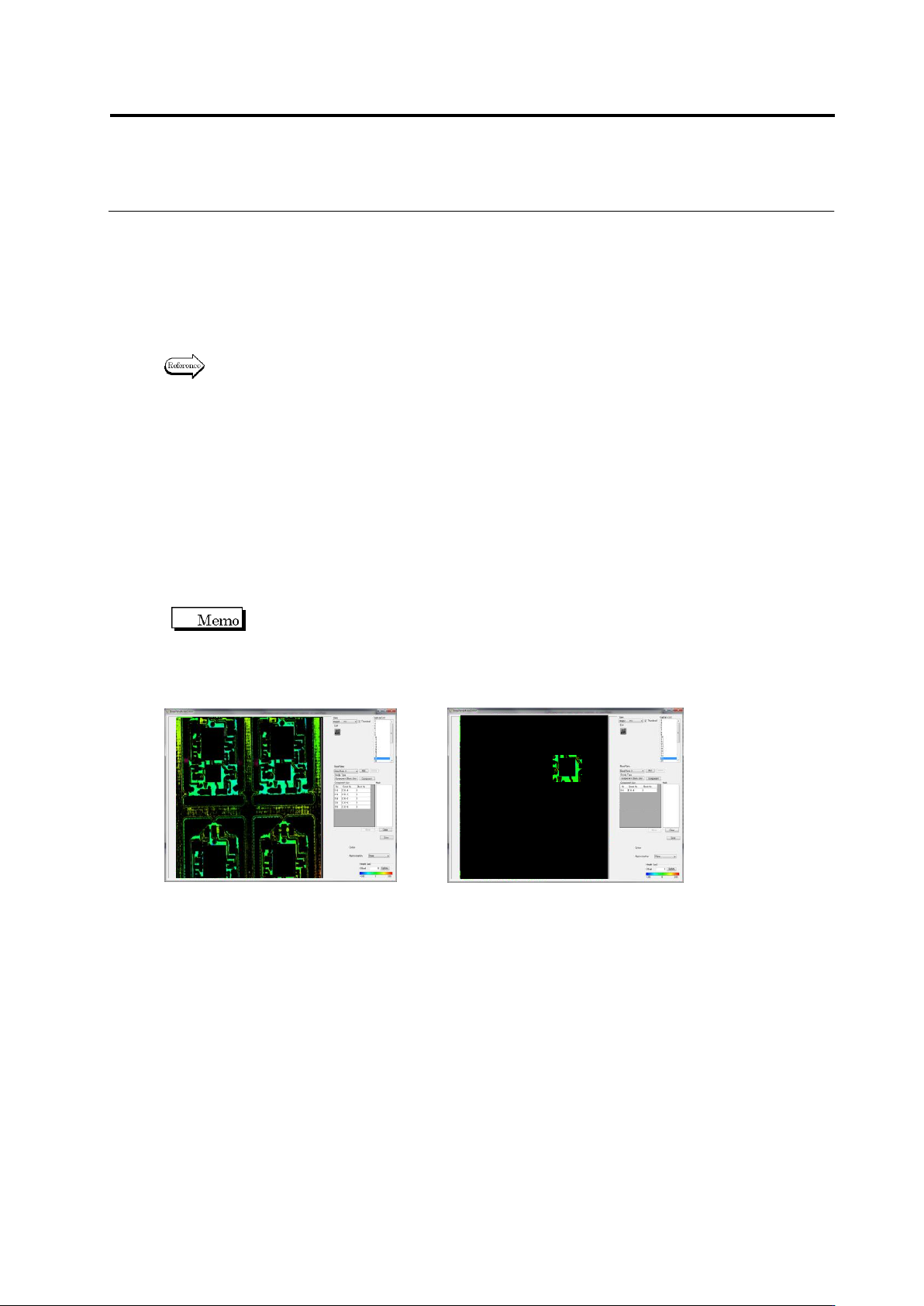
<Base plane per-block partitioning function>
This function sets up base planes automatically by partitioning them on a component block unit
basis.
To use this function, it is assumed that component block unit has been set up.
By clicking the ⑮ base plane per block partitioning button, the base plane is partitioned in the
overall FOV on a component block unit basis.
Chapter 2 Inspection Programming
2-200
Hereafter the effect of this function is shown.
Before setup After setup
<Base plane manual partitioning function>
This function can generate more than one base plane in a FOV. Use this function when
component block unit has not been set up yet and the base planes have different height.
Use the ⑤ select button to select an area to be partitioned or use the ⑰ component list to
select a component to be applied to base plane partitioning. By clicking the ⑬ add base plane
button after selecting it, it is able to partition or add base planes.
More than one component can be selected by selecting them as pressing and
holding the Ctrl key on the ⑰ component list or on a binarized image.
The added base planes can be resized by the ⑤ select button.
Hereafter, examples of base plane partitioning are shown.
Before partitioning Select component (displayed in white) After partitioning
For the settings of base plane, refer to “Base Plane Partitioning Setup” of Section 2.4
“Base Plane Setup” in the inspection logic manual.
2.16 Managing PCB Images
2-201
<Curved face approximation setup function>
Use this function when the base plane in the inspection image cannot be approximated to a
plane due to distortion of the base plane such as a flexible PCB.
Use the ㉒ base plane approximation method selecting combo box to set this function as
curved face approximation (quadric).
For the settings of base plane, refer to “Curved Face Approximation of Base Plane” of
Section 2.4 “Base Plane Setup” in the inspection logic manual.
<Base plane per-component partitioning function>
This function partitions a base plane on a component basis and sets the partitioned ones
automatically.
Use this function if the height of base planes does not become equal to each other even after
using the ⑮ base plane per-block partitioning function or the ㉒ curved face approximation
setup function. By clicking the ⑯ Component button, the base plane is partitioned in the overall
FOV on a component basis.
To use this function, it is assumed that component block unit has been set up.
Hereafter the effect of this function is shown.
Before setup After setup
4.
Finish editing of the reference level model. To save the edited data,
click the
㉑
Save button, and click the Close (x) button in the upper
right corner of the window to return to the base plane management
image screen.