Omron V-TS Teaching Manual.pdf.pdf - 第284页
Appendix 2. Initial Adjustm ent a-7 Criteria Setting (Com ponent Number) Screen Yes No Yes No No Yes No No Yes Yes No Yes No No Yes Yes Yes No Land error Yes No 1 2 Refer to [Appendix 8. Height Setting Inform ation] Refe…
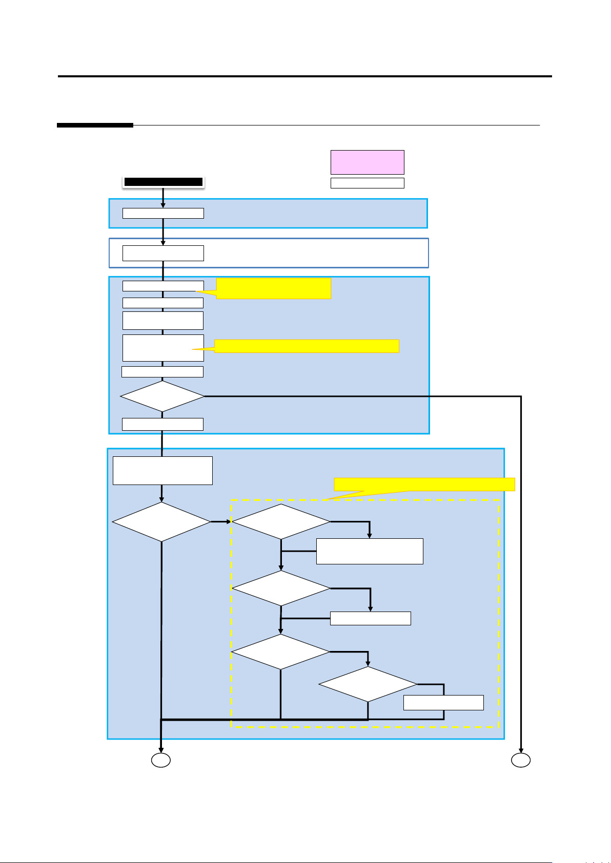
Appendix 2. Initial Adjustment
a-6
Appendix 2. Initial Adjustment
Criteria Setting (Comp. No.) Screen
Result confirmation screen
Machine
Automatic (Internal)
Manual Operation
Save as adjustment
Test PCB
Ye
No
No
Initial adjustment
Refer to [Appendix 5. Real Fault
Registration Procedure]
Yes
Yes
No
Yes
No
Yes
No
1
2
No
Yes
Refer to [Appendix 6. Selection of Optimization Items]
Refer to [Appendix 7. Position Correction/Extraction]
Execute inspection
Register images and real faults
Confirm details of
Check necessary
comp. No. and
select necessary
Test PCB again
Is there
Confirm displacement of each
window information
To Criteria Setting
(Component Number)
Each window has
Extraction size of
comp/electrode/land
windows of comp. image
not appropriate?
Extraction position of
comp/electrode/land
windows of comp.
Check window size (XYZ) from
inspection regist/comp regist
screen
Adjust with characteristic
parameter
Comp. has
oblique side?
Extraction
window not
Set extraction
window
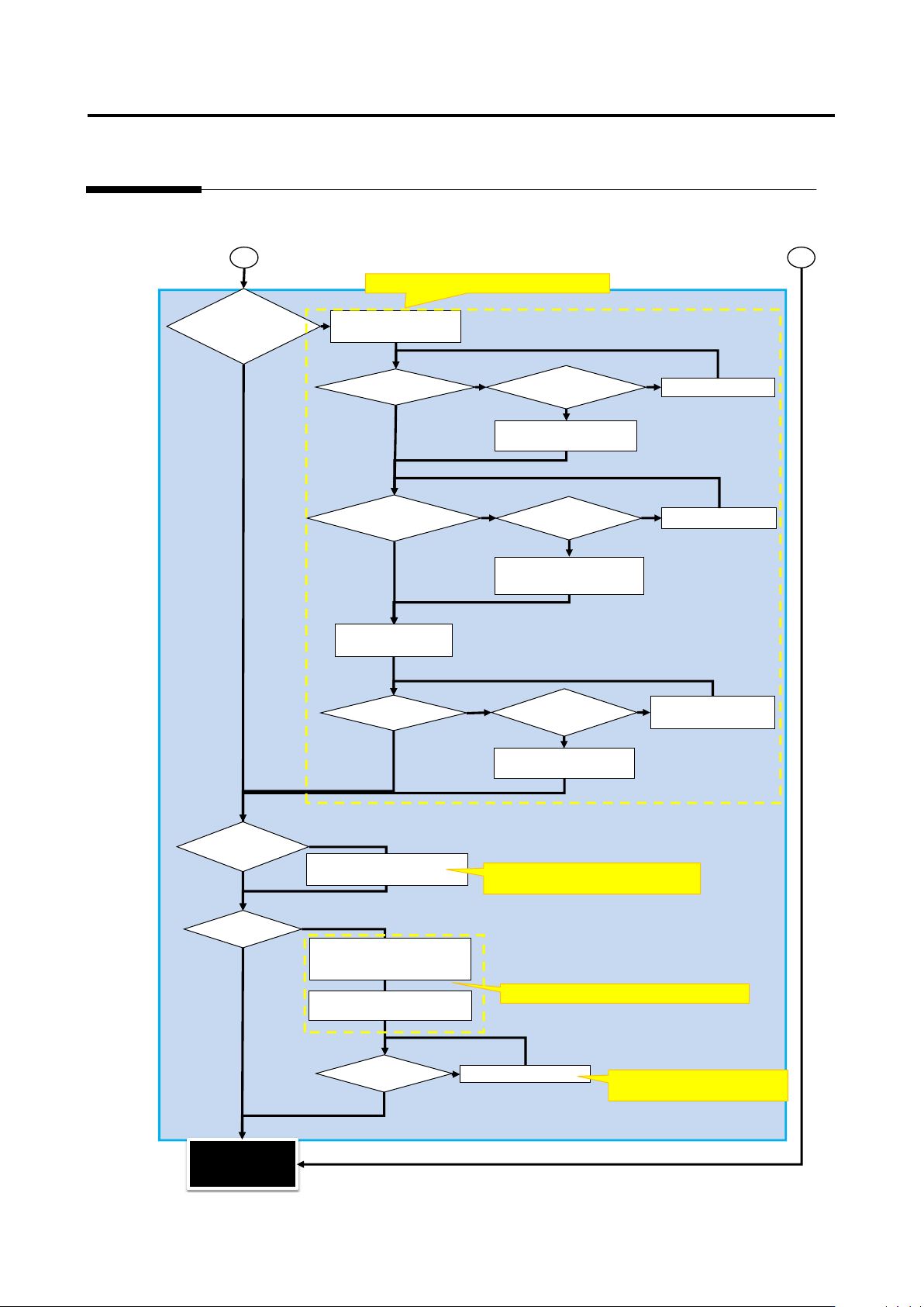
Appendix 2. Initial Adjustment
a-7
Criteria Setting (Component Number) Screen
Yes
No
Yes
No
No
Yes
No
No
Yes
Yes
No
Yes
No
No
Yes
Yes
Yes
No
Land error
Yes
No
1
2
Refer to [Appendix 8. Height Setting Information]
Refer to [Appendix 10. Inspection Criteria Setting]
Refer to [Appendix 9. Land Inspection
Adjustment Procedure]
Refer to [Appendix 9. Land
Inspection Adjustment Procedure]
When fault names
are confirmed, is
there a fault
inspected by height
information?
Compare set height of
comp. information with
Components have
different height?
Comp. height not measured
correctly compared to 3-plane
Adjust position of lifted
window
Change comp. height based
Comp. tilt fault on
Comp. tilt not measured
correctly compared to 3-
plane drawing?
Adjust position of
For components such as
electrolytic capacitors or
Compare set height of comp.
information with resultant
height of OK comp.
Electrodes have
different height?
Electrode height result not
measured correctly
compared to 3-plane
Adjust tip extraction of
electrode window using
characteristic parameters
Change electrode height
based on resultant electrode
Undetected fault and false
call insp. items can be
adjusted using
Adjust characteristic
parameters of applicable insp.
Undetected fault or
false call still detected
Set criteria manually if OK and
NG products appropriately
separated on inspection screen
and difference from set reference
When there is no insp. item but
no problem, deselect the insp.
Undetected fault or
false call still
detected after
Inspection program
release
(Initial adjustment
completed)
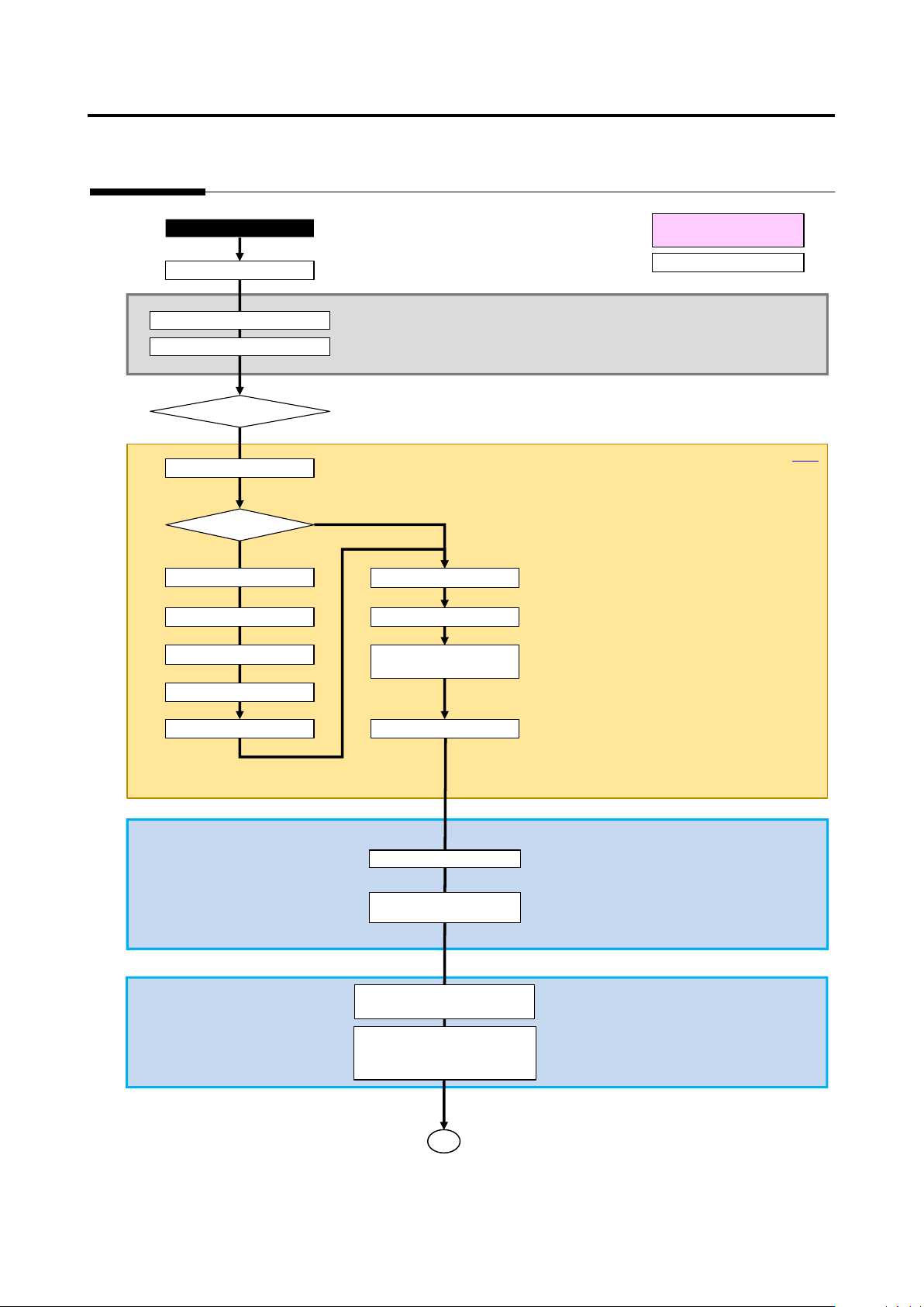
Appendix 3. Mass Production Adjustment (false call minimization)
a-8
Appendix 3. Mass Production Adjustment (false call minimization)
Mass production image registration screen
Result confirmation screen
Q-up
Automatic (internal)
Manual operation
Register insp. fault
Move to false call Pareto
Select false call comp.
Movo to image comparison
Register real fault
Real fault?
Yes
No
v-CA
Execute inspection
False call
Select insp. program/PCB list
Confirm visually and register
Select insp. program
Select fault type
Move to image comparison
Select component
Move to mass production
PCB test (adjustment
Select comp. No. from comp. No.
list, and press "Edit Model"
-> The screen moves to criteria
Read in mass production image
from image management job
1
Mass production adjustment
Move to real fault Pareto