Omron V-TS Teaching Manual.pdf.pdf - 第301页
Appendix 7. Positio n Correction/Extractio n a- 24 If the com ponent has a tilted side Characteristic param eters are not set appropriatel y . (The c omponent body color and electrode color are not being set sufficiently…
Appendix 7. Position Correction/Extraction
a-23
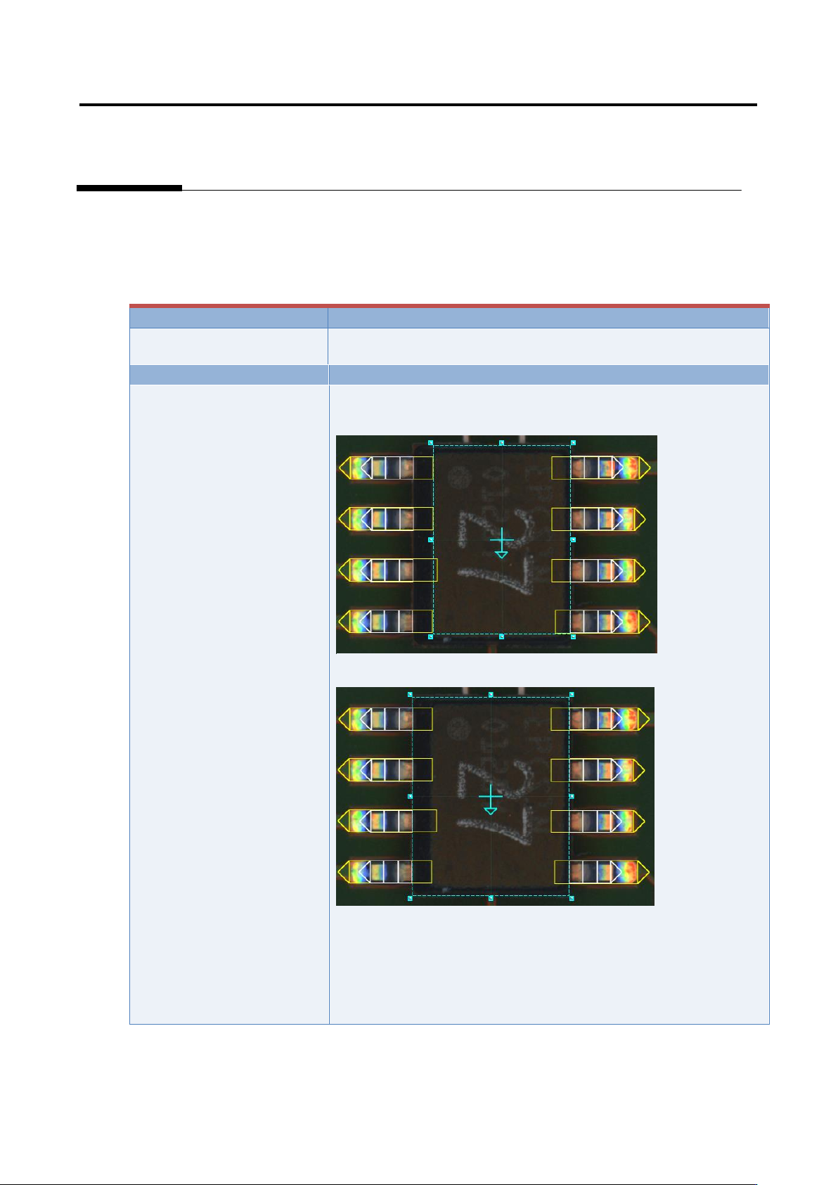
5. Component extraction
A component is extracted in the inspection range window, the positions of the component body window
and electrode window are corrected and specified as the reference positions for the component body
inspection and electrode inspection.
Inspection result
Component image (PCB test)
Cause
Confirmation and repair method
The component body window
and electrode window are not
sized appropriately.
1) Move to the “Inspection Registration” tab.
2) Confirm that the component body window has an appropriate
size.
3) If not appropriate, change the size/position of the component
body window, and click the [Next] button.
4) Click the [Next] button.
5) Click the [Next] button.
6) Confirm that the electrode window has a size consistent with
the image.
7) If not consistent, change the electrode window’s size/position.
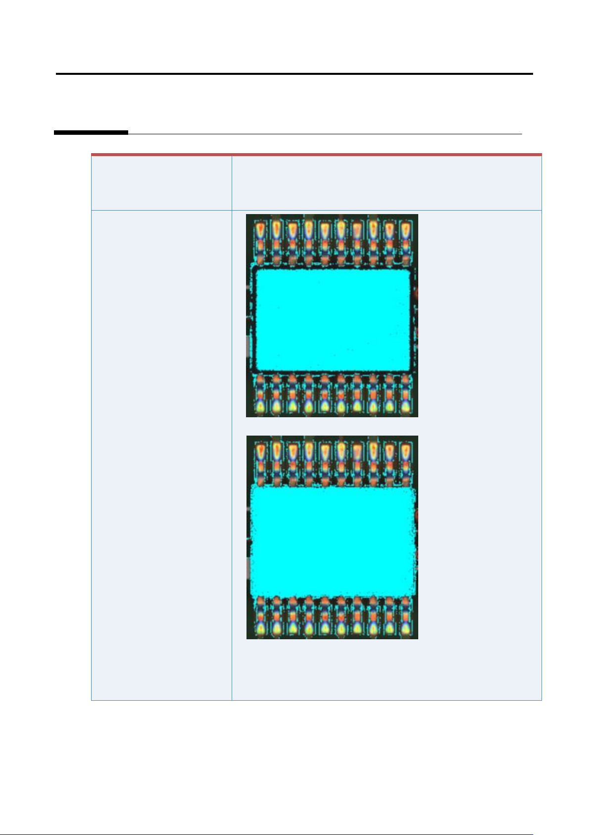
Appendix 7. Position Correction/Extraction
a-24
If the component has a tilted
side
Characteristic parameters
are not set appropriately.
(The component body color
and electrode color are not
being set sufficiently.)
1) Set the parameters if not set.
2) Select “Inspection Criteria” - “Extract Electrode Tip,” and click
the [Model Editing] button.
3) Confirm if the electrode color is being set.
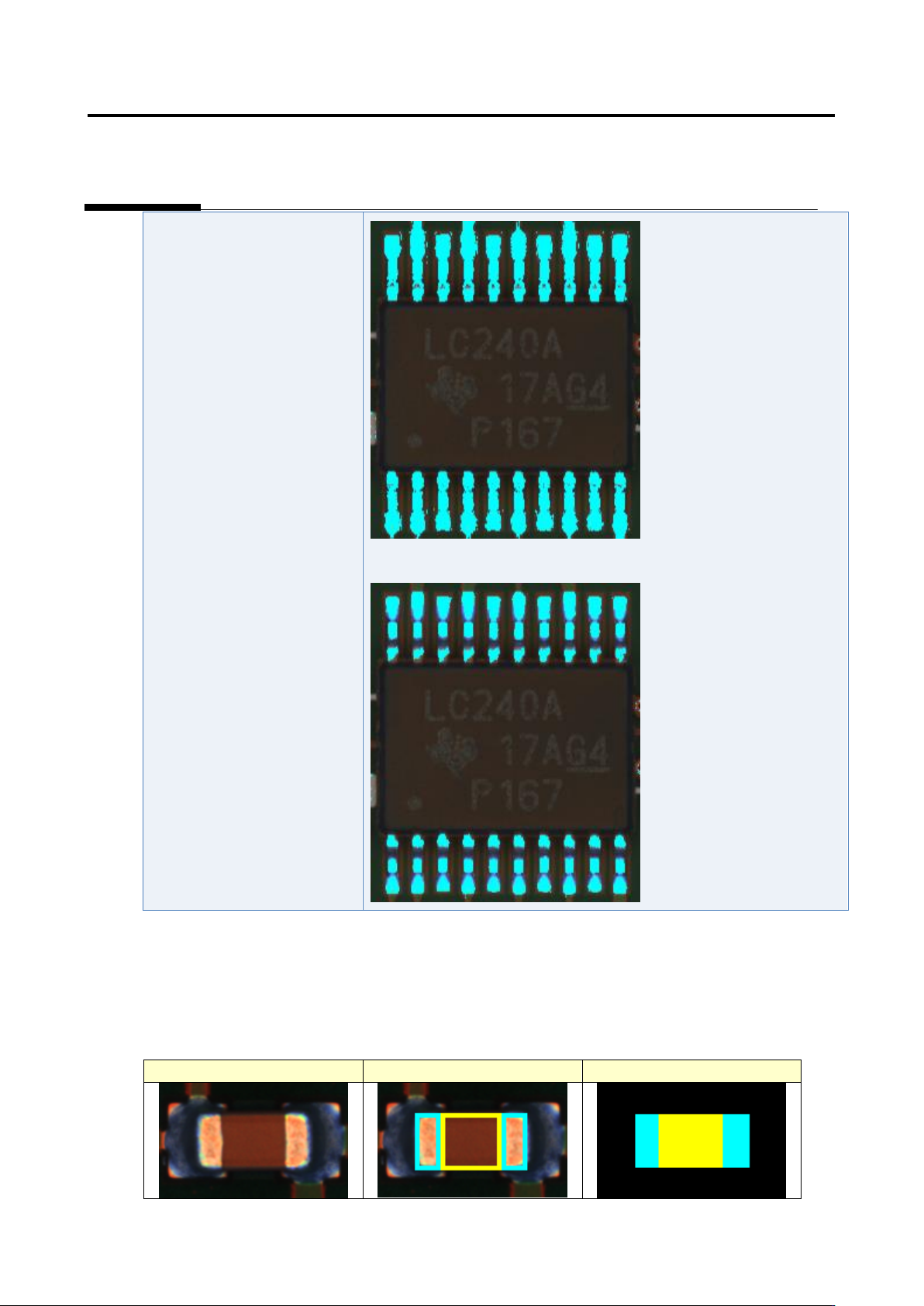
Appendix 7. Position Correction/Extraction
a-25
4) Set the parameters if not set.
Details of the procedure to adjust component extraction using characteristic parameters are as follows:
The component extraction function extracts something similar to the component by template (model)
matching. The component extraction model is created based on the window setting like the figure below.
Inspection image
Window setting
Component extraction model