Omron V-TS Teaching Manual.pdf.pdf - 第114页
2.6 Specif ying Inspection Criteria 2- 87 Refer to "2.15.3 Editing a Model" for the model editing procedure. W hen setting judgment in com bination of inspection res ult and/or inspection of a com ponent # or w…
Chapter 2 Inspection Programming
2-86
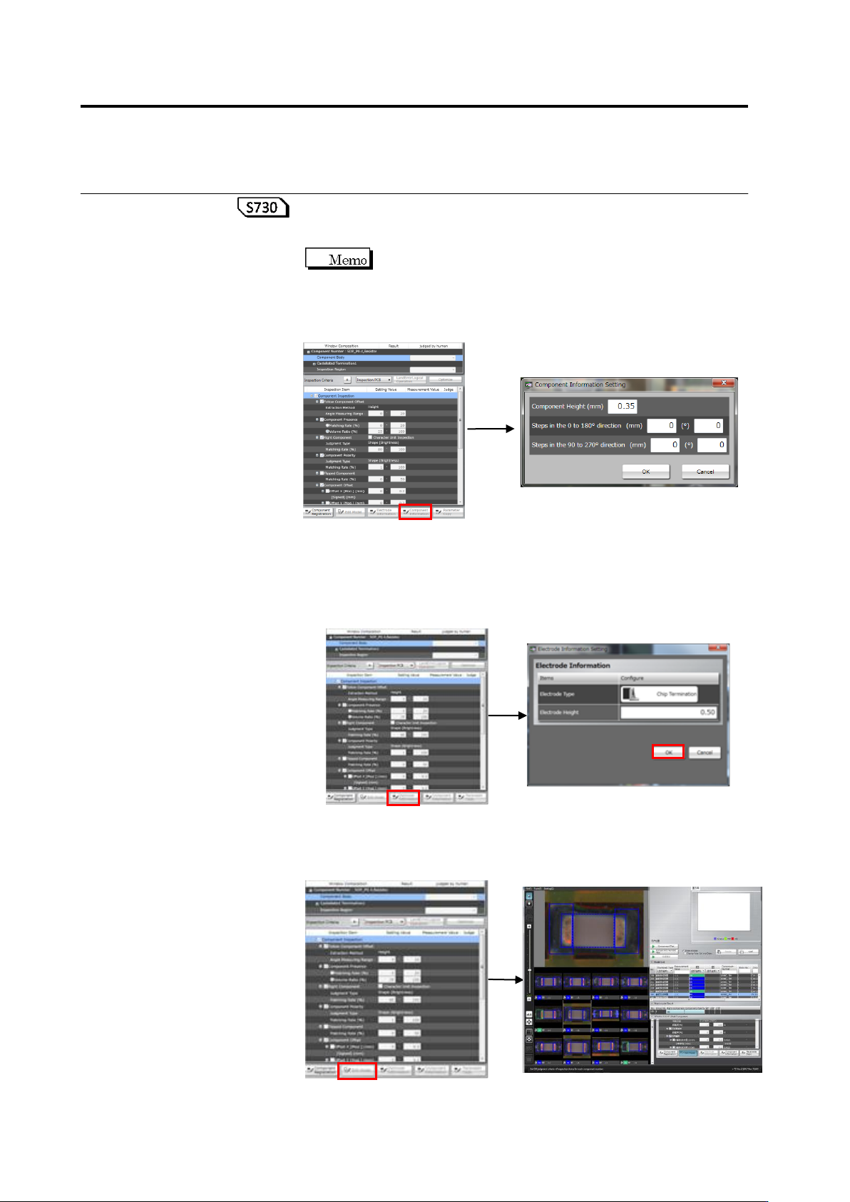
To check or change the component data (height), click [Component
Data]. In the component data setting dialog box, change component
height/component step if necessary, and click [OK].
Enter a value if the component upper surface has unevenness.
Items (mm) and (°) are independent input, respectively, and
whichever being selected by the radio button for the
component lift inspection (height/angle) is applied. If the
measurement point is lower than the reference point, enter the
value of unevenness as a numerical value using “-“.
To check or edit the electrode information, click the target electrode
group in the Window Composition to select it, and click [Electrode
Information]. The Electrode Information Setting dialog appears.
Change the electrode height as required and click [OK].
For manually editing the characteristic parameters automatically
extracted in model calculation, click the target inspection item and
click [Edit Model].
2.6 Specifying Inspection Criteria
2-87
Refer to "2.15.3 Editing a Model" for the model editing procedure.
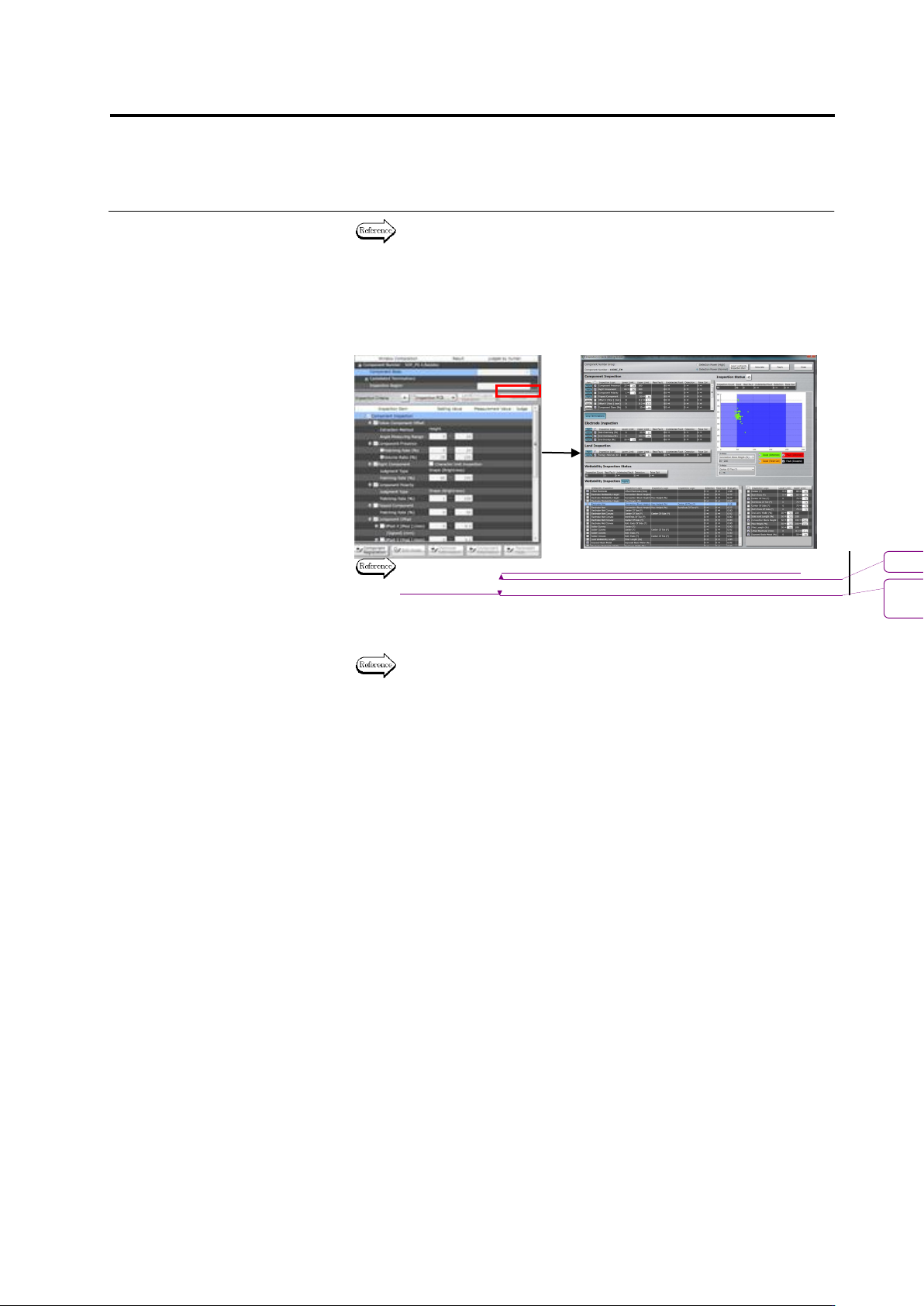
When setting judgment in combination of inspection result and/or
inspection of a component # or whole component # group with the
inspection result, click [Optimize]. The inspection criteria detail
setting screen appears. Set a Boolean expression as needed and
click [Apply].
Refer to “2.15.4 Optimizing Boolean Expressions and Inspection
Criterion Values” for setting procedure.
6.
Repeat Steps 2 to 5 for all the component numbers.
Refer to “2.15.3 Editing a Model” for deployment.
書式変更: フォント : 9 pt
削除
: Optimizing Boolean Expressions
and Inspection Criterion Values
Chapter 2 Inspection Programming
2-88
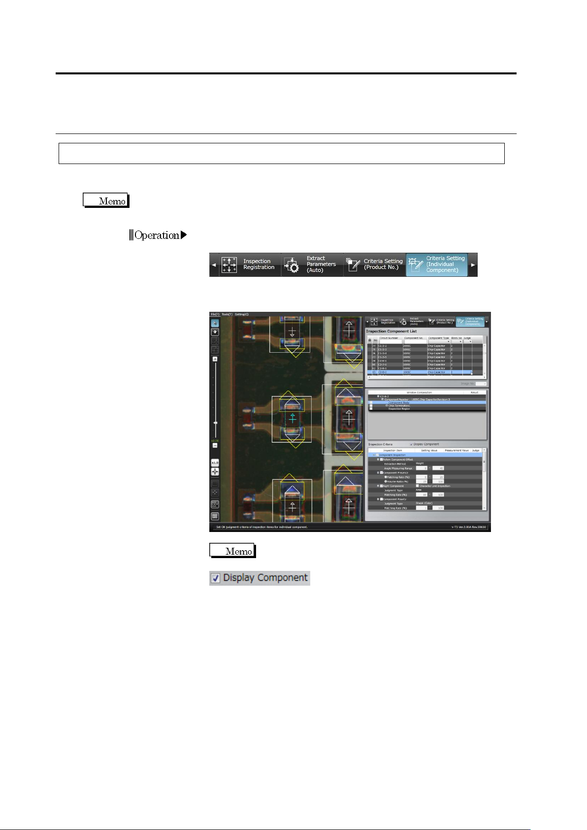
2.6.2 Criteria Setting (Individual Component)
Inspection criteria can also be specified for individual components or windows independently from
the component numbers.
In individual component criteria setting, each of land windows and electrode windows can be
specified individually.
1.
Select the [Criteria Setting (Individual Component)] tab to display
the Criteria Setting screen.
2.
Select the component for individual setting in the Inspection
Component List.
Switch between an Inspection PCB image and an
Unpopulated PCB image by clicking ON/OFF in the
check box.
Operation