Omron V-TS Teaching Manual.pdf.pdf - 第72页
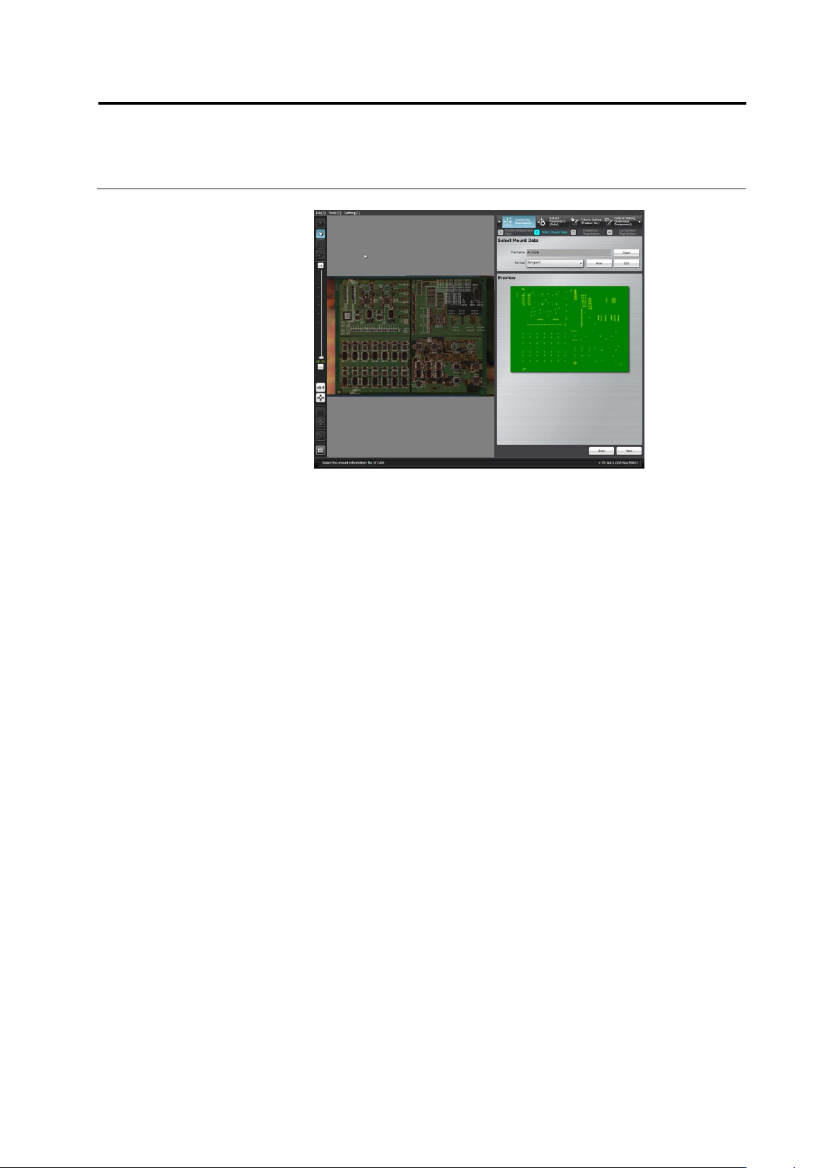
2.4 Registeri ng f or Insp ection 2- 45 4. Click [Next] to m ove to the Mount Alignm ent screen.
Chapter 2 Inspection Programming
2-44
■ Data Separation
Specify the method of delimiting the data.
Mount data must be separated into the six items including X
coordinate, Y coordinate, angle, circuit number, component
number, and explanation.
Explanation is not indispensable. Specify it arbitrarily.
Split data by character(s)
The data is separated by the specified delimiting character.
Specify the delimiting character and the ordinal number of
the delimiter (nth string) where each data item starts.
Split data by position
The data is separated into sets of the specified numbers of
characters.
Specify the ordinal numbers of the characters (from n to n +
the number of characters) where each item starts and ends.
■ Unit Conversion
Convert the unit of the X and Y coordinates of the mount data
from mm (if it is used) to μm by multiplying the value by 1000
(1000 x Data). The angle must be converted to the value in the
counterclockwise direction (-1 x Data + 0) if it is represented in the
clockwise angle.
Values up to 8 digits and 3 decimal places either in positive and
negative numbers can be entered.
■ Data View
Check if the individual data items are separated correctly.
Click [Preview] to display the data separation view obtained by
the setting.
The coordinate values are rounded at the 4th decimal place.
The angle is represented in 0 to 359 degrees, with the decimal
1st place rounded. A value exceeding 360 degrees or negative
value is converted to the value in 0 to 359 degrees.
The alphabets in the circuit number and component number are
expressed in upper case letters.
The effective numbers of characters for the circuit number and
component number are up to 16 and 64 characters respectively.
If the numbers exceed the limits, an error dialog appears and no
data is displayed for the items in the data view.
The symbols that can be used for the circuit number and
component number are as follows:
! # $ % & ' ( ) - = ^
~
@` [ { ;+ } ] ,._
␣
If the symbols not allowed (¥|:*<>/?) are used, the data view
displays no data for the item. If a slash is used, it will be
converted to a hyphen (-). The quotation marks (") at the head
and end of the entire string are ignored and only the string is
displayed. However, if the mark is used inside the string, no data
is displayed for the item in the data view.
Click [Save]. The format setting is saved and the dialog is closed.
Clicking [Cancel] aborts the setting and closes the dialog.
Click [Delete] to delete the format being edited and close the dialog.
Chapter 2 Inspection Programming
2-46
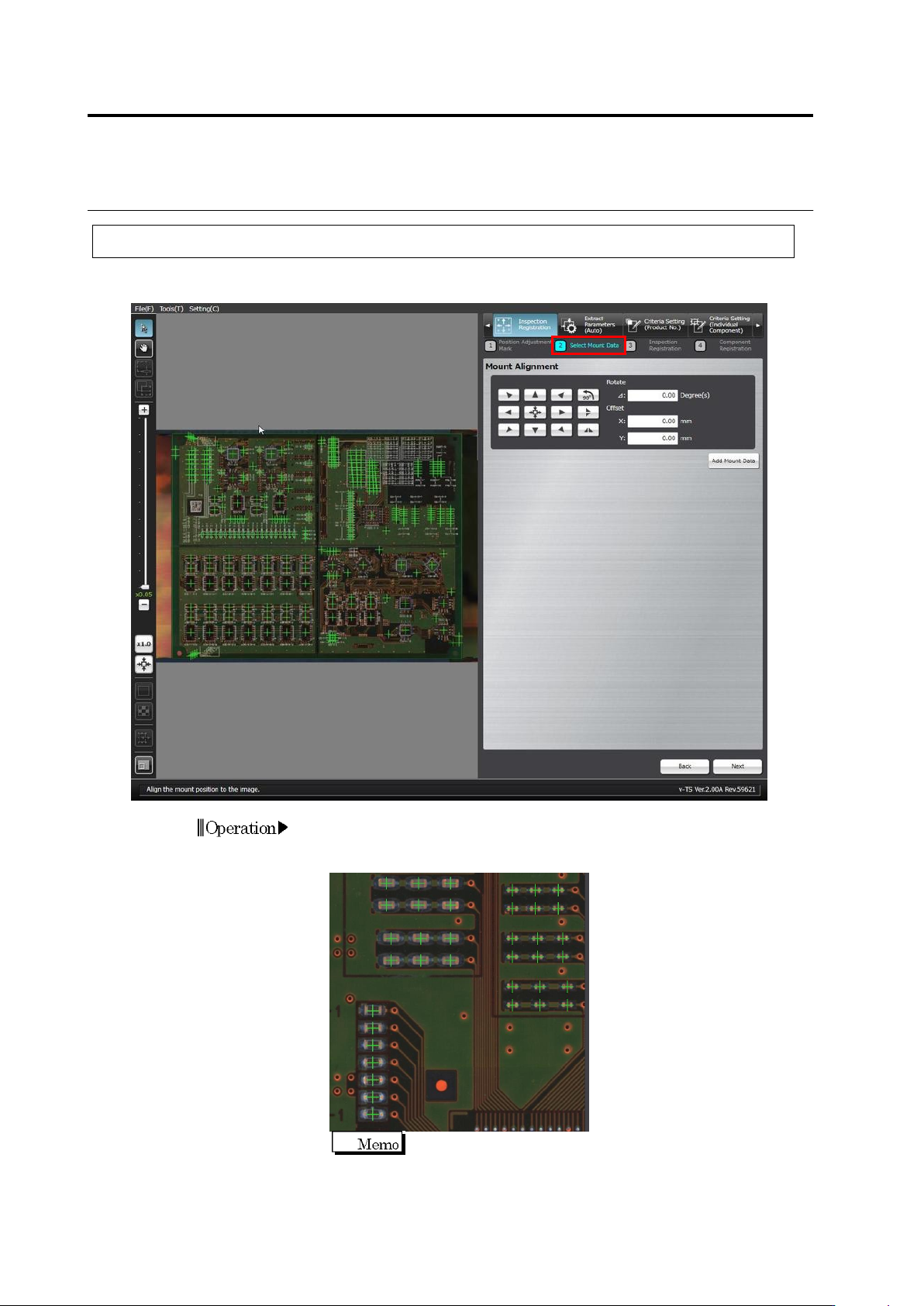
2.4.3 Mount Alignment
Align the coordinates of individual components in the mount data (loaded in the previous section)
to the PCB image.
1.
The mount positions shown by "+" marks are overlaid on the PCB
image. Use the buttons or the mouse to align the "+" marks at the
centers of the corresponding components on the PCB image.
For precise alignment, enlarge the PCB image and shift the
field of vision to check that "+" marks are also aligned at the
centers of the corresponding components in a different field of
vision.
Operation